originally created by Britt Baugher for Jarillo-Herrero Group
Introduction
It has been shown that you can quantitatively determine the number or layers of few layer graphene (about 1-5 layers thick) on 300 nm thick SiO2 simply using an optical microscope and some post processing software. The interference effect that allows us to distinguish different graphene thicknesses by eye can be easily read by the computer to give a more quantitative analysis of the layer number. This is accomplished by reading the intensity of green light reflected by the bare SiO2 substrate and by the graphene flake, and calculating the difference between the two. The interference of reflected light formed between graphene and the SiO2 substrate peaks in contrast at 560 nm, right in the green spectrum of light. The green pixel in an RGB monitor is peaked very close to this value at roughly 510 nm. Thus, by simply reading off the difference in the G value between the light reflected by the graphene and the bare substrate we can selectively pull out graphene's contrast. The contrast of single layers of graphene are expected to add linearly. Thus, this works to pick out single layer graphene from the substrate as well as mono-layer from bi-layer, bi-layer from tri-layer, and so on up to about five layers thick.
ΔG Statistics
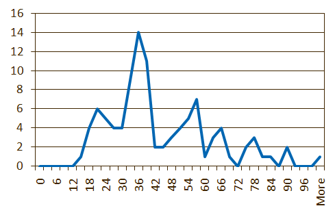
Layers |
ΔG |
|---|---|
1 |
21 |
2 |
36 |
3 |
57 |
4 |
66 |
5 |
78 |
How to determine graphene layer # by measuring ΔG
- Take pictures of graphene and the substrate on the optical microscope.
- To get consistent results that match with each other as well as with past results you must take all of your pictures at exactly the same settings. The current settings are:
*These values are meant to set the color of SiO2 to white. The easiest way to get to get these values is to click the interactive button and then choose a spot of bare substrate with the eyedropper. This will get you close, then adjust from there with the arrows.
Parameter
Value
Parameter
Value
Lamp
3200K
Brightness
-0.67
A Aperture
Fully Open
Contrast
1.44
1st Filter
100
λ
1.00
2nd Filter
100
Cyan*
1.23
F Aperture
Fully Open
Magenta*
1.07
Polarizer
Out
Yellow*
0.70
BF/DF
Bright Field
Exposure
112 ms
Magnification
1000x
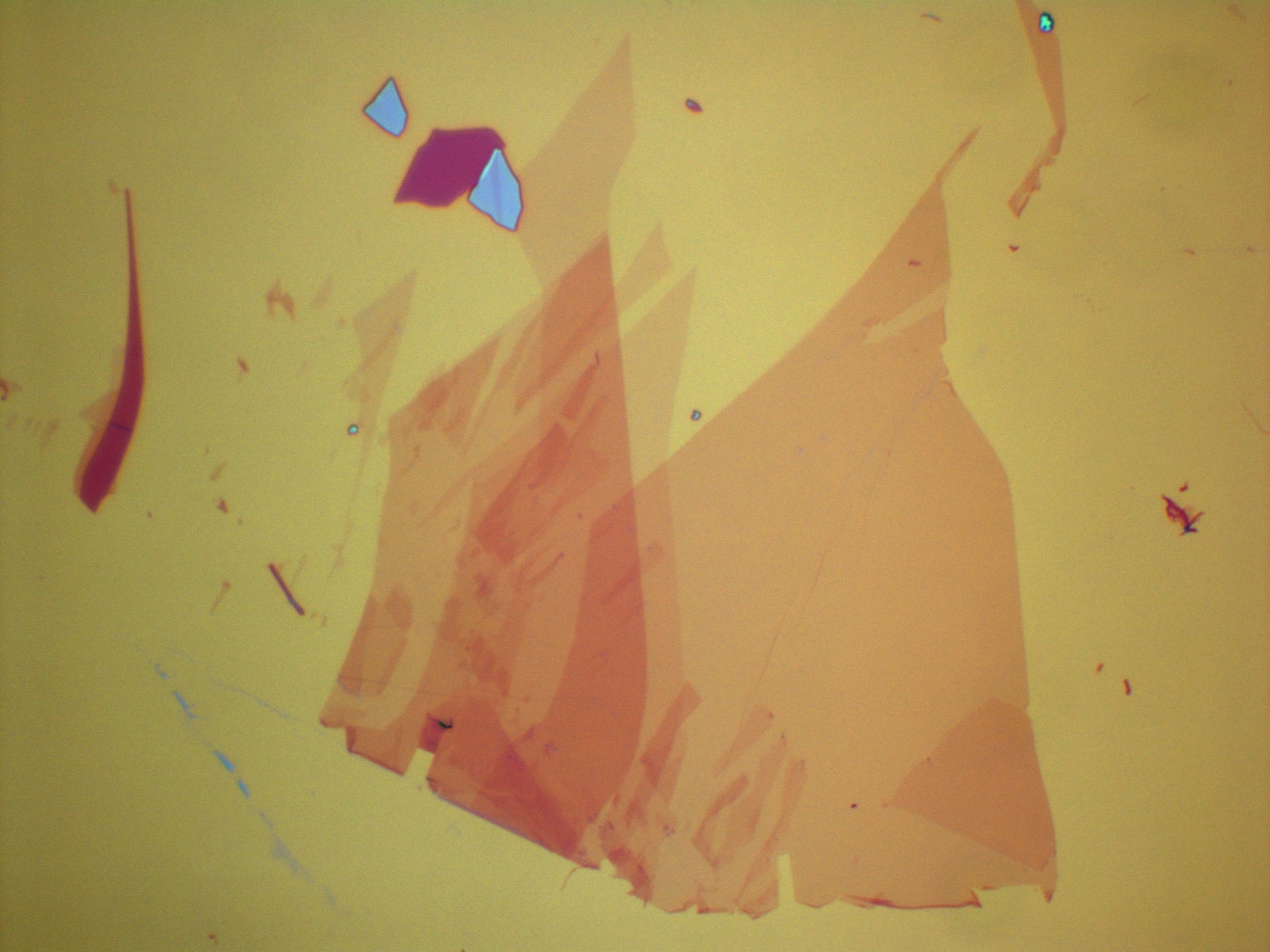
Your images should look similar to this:
- Take a picture of the blank substrate under these settings. Try to find an area with no graphene, graphite, or glue residue in it. If you can't find a perfectly clean area take additional pictures where the junk is in a different part of the picture. You can combine them later to make one clean picture.
- Save all your graphene pictures and your substrate pictures as jpegs
- To get consistent results that match with each other as well as with past results you must take all of your pictures at exactly the same settings. The current settings are:
- Make a clean background image:
- Open your substrate pictures in Photoshop
- Copy and paste all of the substrate pictures on top of each other.
- Erase any defects layer by layer until the composite image is a clean background.
- Press Ctrl+E to merge all the layers into one.
- Go to Filter-Blur-Smart Blur and input these settings:
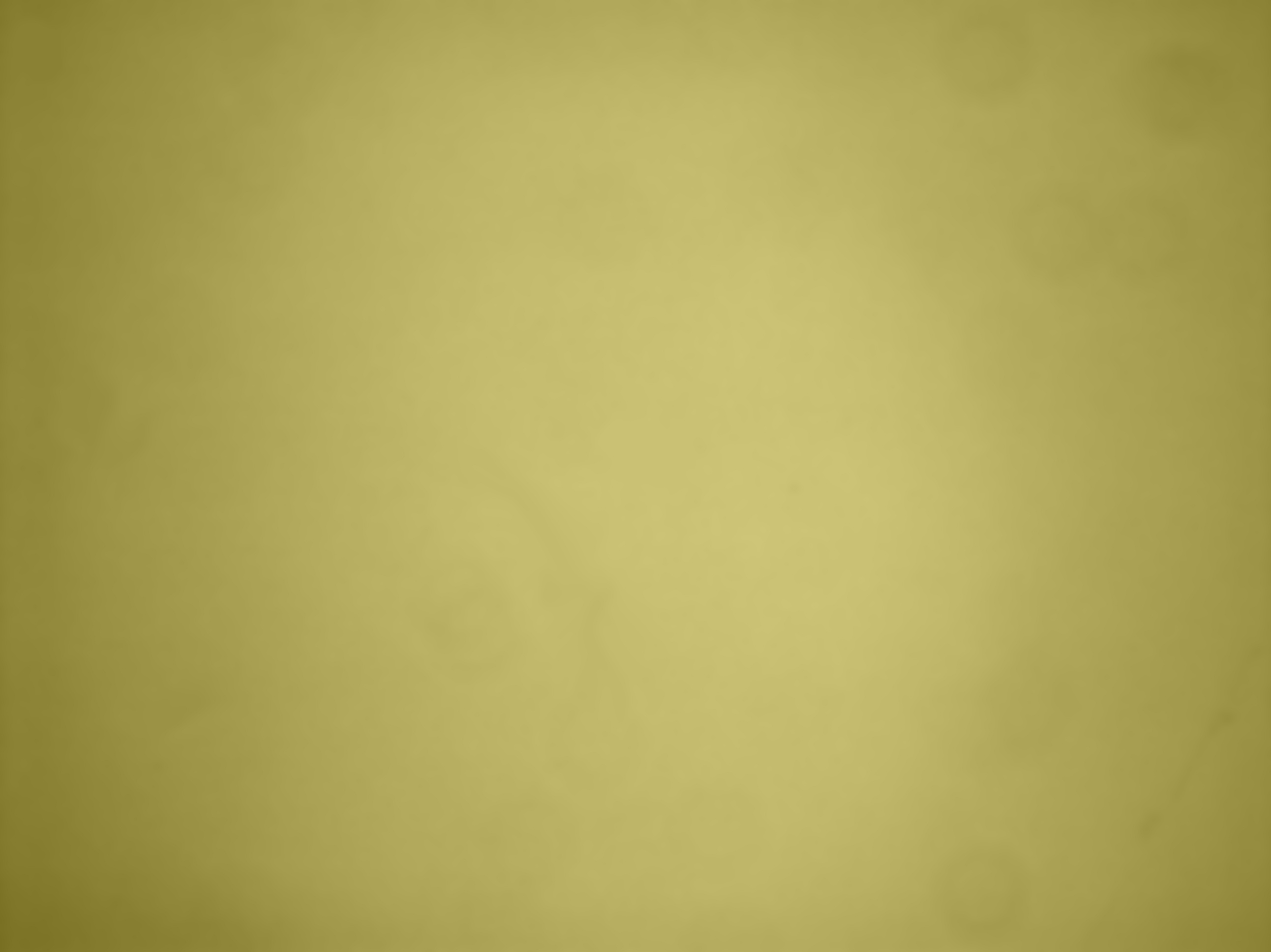
It should come out looking something like this:
Parameter
Value
Radius
25
Threshold
20
Quality
High
Mode
Normal
- Select the image and copy it.
- Subtract the background from your graphene pictures
- Open your first picture of graphene.
- Create an action sequence that you can replay on each image.
- Press Alt+F9 to open the Actions Window.
- Click on the Create New Action button on the bottom of the Action Window.
- Name it something like "Color ID", and if you want, set a function key as a shortcut to run it.
- Press Record. n.b. From now on every mouse click will be recorded in this action so follow the next instructions precisely.
- Press Ctrl+V to paste the background image over the graphene image.
- In the layers window click the drop down menu that says Normal and select Difference.
- Press Ctrl+E to merge the two layers.
- Go to Filter-Blur-Smart Blur and input the settings above and click OK.
- Click the Stop button on the bottom of the Actions Window.
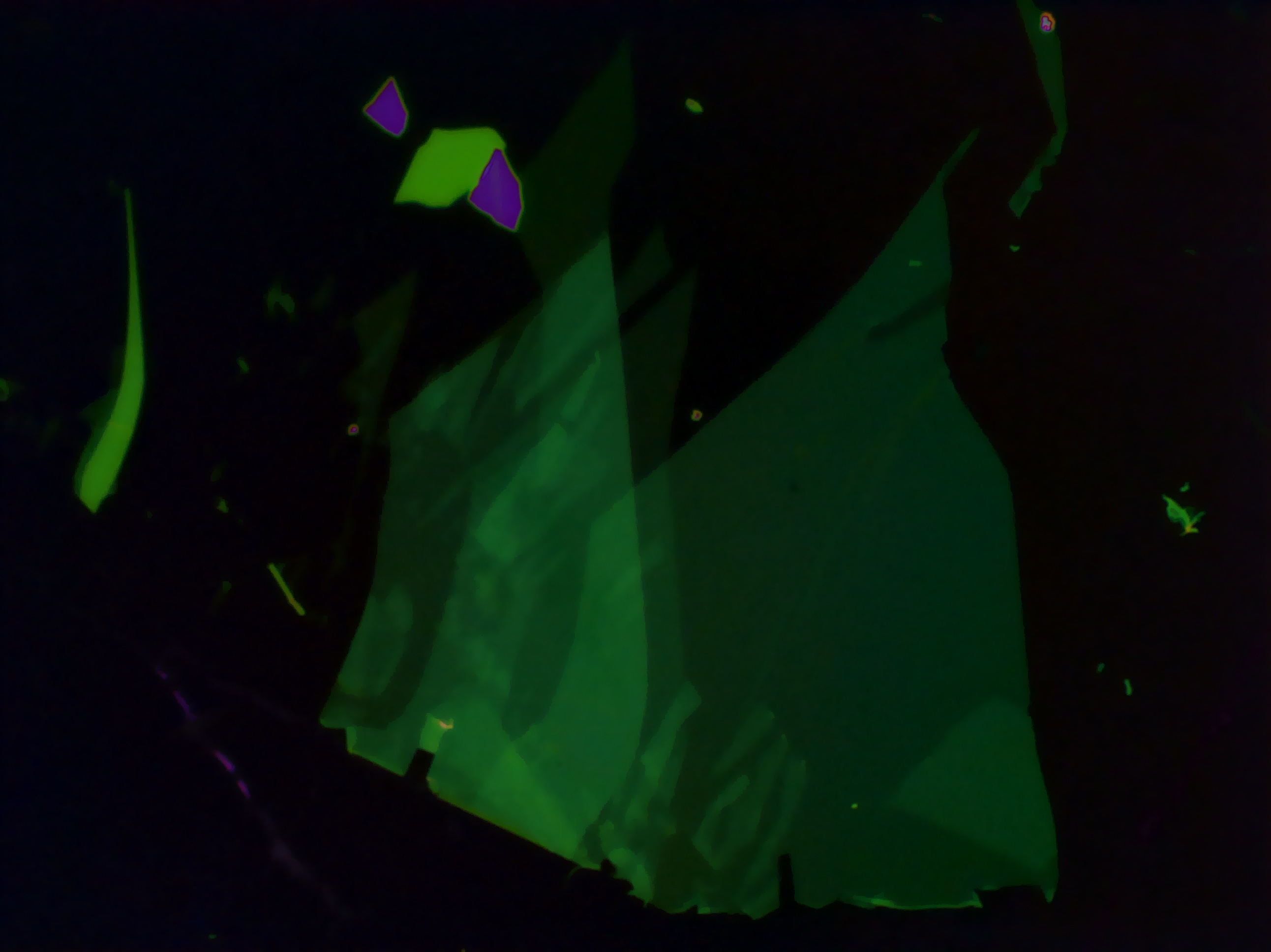
- You should now have an image with graphene layers that stand out in different shades of green on top of a black background.
Something like this:
- Take color measurements.
- Press F8 to open the Info Window.
- Go to the Tool Bar on the left side of the screen and select the Lasso Tool or the Rectangular Marquee Tool. (L is the shortcut for the Lasso Tool and M is the shortcut for the Rectangular Marquee Tool.)
- Select the largest clean area on the graphene layer of interest you can.
- Go to Filter-Blur-Average. n.b. After doing this once, Ctrl+F will preform an averaging filter.
- Simply hover over the area you just averaged and read the G value off the Info Window.
References
Double-gated graphene-based devices
Rayleigh Imaging of Graphene and Graphene Layers
—