Versions Compared

Key

  • This line was added.
  • This line was removed.
  • Formatting was changed.

...

Section
Column
width500px

LED Control:

DOUT1 - pin1 on motor driver DB15 connector
+5V taken from LED driver 


External connector shared with e-stop:
Bottom right - LED + 
Bottom left - LED -  

Column
width500px

Motor Driver:

Roboteq I/O connector:
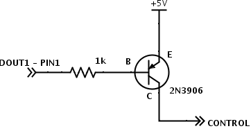
1 - DOUT1 - see led control above
2 - TX - green - top left on cpu connector
3 - rx - blue - top right on cpu connector
4 - DIN1 - e-stop - top right on e-stop connector
13 - gnd -  power switch led gnd
14 - 5v - power switch led + and e-stop top left 

CPU Box Connector:
top left - green - roboteq tx - roboteq I/O pin 2
top right - blue - roboteq rx - roboteq I/O pin 3
bottom left - power ground
bottom right - power vbatt

Power Switch Wiring:
C1 - power control
NO - vbatt
NC - ground
LED+ - roboteq i/o pin 14 (5v)
LED- - roboteq i/o pin 13 (gnd)

main power plugs put positive on the right, ground on the left
batteries use the opposite (positive on left, ground on right)
batteries also use center pin for balance ground, then highest voltage top right decreasing clockwise (lowest/first cell top left) 

...

CPU Box:

Section

Arduino Shield <-> Power Board

Column
width500px
linePower Board LabelArduino LabelArduino Pin

Radio power control

Sense

unwired

A4

Servo power control

6v

RAUX

A3

Vbat control

Not labeled

unwired

A2

12v control

12v

R12

A1

Servo pwm

Servo

SRVO

A0

gnd

Gnd

GND

GND

+5

vin                 

5v

5v

power reset

Not labeled

VBAT

12

radio power control is no longer used as of radio box redesign in january 2015

...