ObjectivePlace a vibration sensor on the flight test for the Hermes II rocket in order to: - measure vibration characteristics at nose cone of rocket, to identify problematic oscillations that could break structure / destabilize rocket
- measure vibration characteristics at the payload module, to determine if countermeasures against vibrations are necessary for future payloads on Hermes II
Vibration in solid motor rocketsNike rockets (1970s)A 1971 report from NASA put a vibrometer on a solid-propellant rocket on a captive (stationary) flight. Vibrometer 6 was located on the payload section(to measure longitudinal response), so its measurements can give an idea of the vibrations in our case. The rocket used was a Nike type M88, with thrust 213kN and 3.4sec burning time, with 705.2kg total weight. This is significantly (x10) heavier than Hermes. The vibrometer could measure vibrations up to 20kHz. The spectral density graph shows a peak at around 10kHz, and the peak is around 40g. 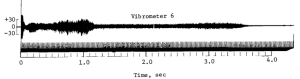
A 1975 report by the same person measured the vibration in actual flight as well. However, the vibrometer could only measure up to 5kH, due to “instrumentation system limitations”. 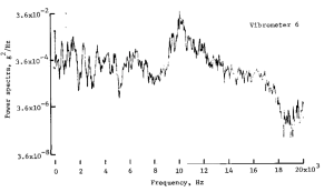
Acceleration profilemax acceleration is ~700 ft/s2, about 20g. This could change later in design.
Heating of nose coneSince the nose cone heats up during flight, it may go over the operating temperature of the instruments. Around the middle of the nose cone, the temperature at the surface is around 370K (100 degrees Celcius). RequirementsConsidering the results of the 1971 report, we should try to choose an accelerometer that can measure vibrations with a frequency of 10kHz. A range of 20kHz, the same as the 1971 report, should give us a comfortably wide range(which is apparently really high! Most accelerometers don’t have such a high range). The acceleration load during launch is max 20g, and the 1971 report suggests that there could be vibrations with up to 40g peaks. A range of 80g should be enough. max measurable frequency | 20kHz | measurement range | 80g | temperature | 100℃ |
COTS sensorsAccelerometersThis sensor is interesting in that it is very integrated- it has 3 axes, and includes FFT analysis and an onboard memory so the vibration spectrum could be directly read out later. Unfortunately, it has a 5kHz flat frequency band with 20g range so it’s doesn’t meet our requirements…
20kHz frequency limit 150g range single axis analog output
linear frequency response up to 23kHz 100g range single axis analog output Available in 5mm x 5mm x 1.8mm LFCSP package (really small), but offers evaluation kit that is basically an adapter to a PCB
Analog-digital converters1MSPS sampling rate TSSOP package, which is also really small(0.5mm pitch), but adapters exist to convert it to DIP package SPI interface- most microcontrollers already support this, though there may be issues with high-bandwidth data
|