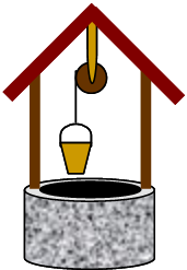
{excerpt:hidden=true}A mass falling while attached to a massive pulley.{excerpt}

!well.png!
{composition-setup}{composition-setup}

A bucket for collecting water from a well is suspended by a rope which is wound around a pulley.  The empty bucket has a mass of 2.0 kg, and the pulley is essentially a uniform cylinder of mass 3.0 kg on a frictionless axle.  Suppose a person drops the bucket (from rest) into the well.


{deck:id=bigdeck}
{card:label=Part A}
h3. Part A

What is the bucket's [acceleration] as it falls?

h4. Solution

We will consider two different methods to obtain the solution.


{deck:id=littledeck}
{card:label=Method 1: Dynamics}

h4. Method 1: Dynamics

{toggle-cloak:id=sysa1} *Systems:*  {cloak:id=sysa1}The pulley and the bucket are treated as separate objects.  The bucket can be treated as a [point particle], but the pulley must be treated as a [rigid body]. {cloak}

{toggle-cloak:id=inta1} *Interactions:*  {cloak:id=inta1}The pulley and the bucket are each subject to [external influences|external force] from the rope ([tension]) and from the earth ([gravity|gravity (near-earth)]).  The pulley is also subject to a [force] from the axle, but we will choose the axle as the axis of rotation so the axle [force] produces no [torque|torque (single-axis)] (it has zero [moment arm]). {cloak}

{toggle-cloak:id=moda1} *Model:* {cloak:id=moda1}[Single-Axis Rotation of a Rigid Body] and [Point Particle Dynamics]{cloak}

{toggle-cloak:id=appa1} *Approach:*

{cloak:id=appa1}

{toggle-cloak:id=diaga1} {color:red} *Diagrammatic Representation* {color}

{cloak:id=diaga1}
We begin with [free body diagrams|free body diagram] for the two objects.

!wellfbd.jpg!

{note}Note that the two forces acting on the bucket each have zero [moment arm] relative to the center of mass of the bucket.  Thus, they have no tendency to produce rotation about the center of mass and so we can justifiably treat the bucket as a point particle.{note}

{cloak:diaga1}
{toggle-cloak:id=matha1} {color:red} *Mathematical Representation* {color}

{cloak:id=matha1}

For the bucket, we write [Newton's 2nd Law|Newton's Second Law]:

{latex}\begin{large} \[ m_{b}g - T = m_{b}a_{b} \] \end{large}{latex}

For the pulley, there will be no translation, only rotation about the center of mass.  We sum the [torques|torque (single-axis)] about the fixed axis defined by the axle:

{latex}\begin{large} \[ TR = I_{p}\alpha_{p} \] \end{large}{latex}

We now make the assumption that the rope does not stretch or slip as it unwinds.  These assumptions allow us to relate the rotation rate of the pulley to the motion of the bucket:

{latex}\begin{large}\[ \alpha_{p} R = a_{b} \]\end{large}{latex}

With this assumption, we can solve the system of equations to obtain:

{latex}\begin{large} \[ a_{b} = \frac{g}{1+\frac{\displaystyle I_{p}}{\displaystyle m_{b}R^{2}}} \] \end{large}{latex}

{warning}Note that _I_~_p_~/(_m_~_b_~_R_^2^) is *not* equal to 1/2.  The ratio of the pulley's moment of intertia to the _pulley's_ mass times radius squared is 1/2, but we have the ratio of the pulley's moment of inertia to the _bucket's_ mass times the pulley's radius squared.{warning}

or, using the formula for the [moment of inertia] of a cylinder:

{latex}\begin{large}\[ a_{b} = \frac{g}{1+\frac{\displaystyle m_{p}}{\displaystyle 2m_{b}}} = \mbox{5.6 m/s}^{2}\]\end{large}{latex}

{tip}As expected, the acceleration approaches _g_ if the mass of the bucket goes to infinity, and it approaches zero if the mass of the pulley goes to infinity.{tip}
{cloak:matha1}
{cloak:appa1}

{card:Method 1: Dynamics}
{card:label=Method 2: Angular Momentum}

h4. Method 2:  Angular Momentum

{toggle-cloak:id=sysa2} *System:*  {cloak:id=sysa2}An alternate approach is to combine the bucket and the pulley into a single system.{cloak}

{toggle-cloak:id=inta2} *Interactions:* {cloak:id=inta2}The system is subject to external forces from the earth acting on the bucket and the pulley (gravity) and from the axle acting on the pulley (contact force).  If we choose the axis of rotation to coincide with the axle of the pulley, then the axle's force and gravity acting on the pulley each produce no torque.  We need only consider the effects of gravity acting on the bucket. {cloak}

{toggle-cloak:id=moda2} *Model:* {cloak:id=moda2}[Angular Momentum and External Torque about a Single Axis]{cloak}

{toggle-cloak:id=appa2} *Approach:*

{cloak:id=appa2}
The angular momentum of the system can be expressed by summing the angular momentum of the parts.  The pulley's contribution is _I_~_p_~ ω~_p_~.  The bucket can effectively be treated as a point particle, so it will contribute:

{latex}\begin{large}\[ L_{\rm axis} = m\vec{r}_{\rm cm,axis}\times\vec{v}_{\rm cm} \] \end{large}{latex}

The total angular momentum is:

{latex}\begin{large}\[ L_{\rm system} = I_{p}\omega_{p} + m_{b}v_{b}R \]\end{large}{latex}

We now assume that the rope does not stretch or slip, allowing us to relate the rotational speed of the pulley to the speed of the bucket as it falls:

{latex}\begin{large}\[ \omega_{p} R = v_{b} \]\end{large}{latex}

We then set the sum of external torques equal to the change in angular momentum of the system:

{note}The internal torques certainly cancel _in this case_ because the internal forces share the same [line of action], which guarantees that they have the same [moment arm] regardless of the axis chosen.  Together with Newton's 3rd Law (guaranteeing equal magnitudes and opposite directions for the internal forces) this implies equal and opposite internal torques.{note}

{latex}\begin{large}\[ m_{b}gR = \frac{d}{dt}\left(I_{p} \frac{v_{b}}{R} + m_{b}v_{b}R\right)\] \end{large}{latex}

Now, using the fact that

{latex}\begin{large} \[ a_{b} = \frac{dv_{b}}{dt} \] \end{large}{latex}

lets us solve to find:

{latex}\begin{large} \[ a_{b} = \frac{g}{1 + \frac{\displaystyle I_{p}}{\displaystyle m_{b}R^{2}}} \] \end{large}{latex}

{tip}The same answer as was obtained via method 1.{tip}
{cloak}

{card:Method 2: Dynamics}
{deck:littledeck}
{card:Part A}

{card:label=Part B}
h3. Part B

What is the bucket's speed after falling 5.0 m down the well?

h4. Solution

Again, we will use two methods.

{deck:id=littledeck2}

{card:label=Method 1: Kinematics}
h4. Method 1: Kinematics

{toggle-cloak:id=sysb1} *System:* {cloak:id=sysb1} Bucket as [point particle].{cloak}

{toggle-cloak:id=intb1} *Interactins:* {cloak:id=intb1}External influences from the earth (gravity) and the rope (tension).{cloak}

{toggle-cloak:id=modb1} *Model:* {cloak:id=modb1}[One-Dimensional Motion with Constant Acceleration|1-D Motion (Constant Acceleration)].{cloak}

{toggle-cloak:id=appb1} *Approach:*

{cloak:id=appb1}
To use this method, you must first find the acceleration of the bucket using one of the methods of Part A.  Once that acceleration is in hand, the problem is reduced to kinematics.  The most direct solution is obtained by using:

{latex}\begin{large}\[v_{y}^{2} = v_{y,{\rm i}}^{2} + 2 a_{y} (y-y_{\rm i}) \] \end{large}{latex}

If we assume _y_ = 0 m at the height of release, then:

{latex}\begin{large}\[ v_{y} = \pm \sqrt{2 a_{y} y} \] \end{large}{latex}

The speed of the bucket, then, must be:

{latex}\begin{large}\[ v_{b} = \sqrt{2 (\mbox{5.6 m/s}^{2}) (\mbox{5.0 m})} = \mbox{7.5 m/s} \] \end{large}{latex}

{cloak}
{card:Method 1: Kinematics}
{card:label=Method 2: Energy}

h4. Method 2: Energy

{toggle-cloak:id=sysb2} *System:*  {cloak:id=sysb2}Treat the bucket, pulley and the earth as a single system.{cloak}

{toggle-cloak:id=intb2} *Interactions:* {cloak:id=intb2}Internal interactions of gravity ([conservative|work#nonconservative]) and tension from the rope (non-conservative) plus an external influence from the normal force on the pulley (non-conservative).{cloak}

{toggle-cloak:id=modb2} *Model:* {cloak:id=modb2}[Mechanical Energy, External Work, and Internal Non-Conservative Work].{cloak}

{toggle-cloak:id=appb2} *Approach:*
{cloak:id=appb2}

There will be no _net_ non-conservative work on this system, even though there are non-conservative forces present.  The normal force is a non-conservative external force, but does no work since the pulley experiences no displacement and the normal force has no [moment arm] and so exerts no torque.  The tension forces on the pulley and the block are non-conservative internal forces.  The tension forces _do_ perform work on the system, but the work done by the downward tension on the pulley and the upward tension on the block are equal in size and opposite in sign.  Therefore, their contributions cancel each other to give zero _net_ non-conservative work.

{info}To see that the net work from tension is zero requires us to use two methods of calculating work.  Using force and displacement, you can show that the work done on the bucket is \\ {latex}\[{W}_{b} = - |Ty|\]{latex} \\ where |_y_| is the distance fallen.  To find the work done on the pulley, we must use \\ {latex}\[ W_{p} = \tau (\theta - \theta_{i})\]{latex} \\ but since \\ {latex}\[ \tau = |T|R \]{latex} \\ and (assuming the rope does not slip or stretch) \\ {latex}\[ \theta - \theta_{i} = |y|/R \]{latex} \\ we find that \\ {latex}\[ W_{p} = + |Ty| \]{latex}.{info}

We can now use the conservation of energy, which consists of three parts:

{latex}\begin{large} \[ K_{\rm trans,i} + K_{\rm rot,i} + U_{\rm g,i} = K_{\rm trans,f} + K_{\rm rot,f} + U_{\rm g,f} \] \end{large}{latex}

If we set _h_= 0 to be at the initial position of the bucket, then we can write:

{latex}\begin{large} \[ m_{p}g(-y_{a}) = \frac{1}{2} m_{b}v_{b}^{2} + \frac{1}{2} I_{p}\omega_{p}^{2} + m_{b}g(-y_{b}) + m_{p}g(-y_{a}) \] \end{large}{latex}

{note}Because we chose a coordinate system with the positive y-axis pointing down, we must be sure to include the negative sign on all y-positions when finding _heights_ (which must necessarily increase when moving _upward_).{note}

where _y_~_a_~ denotes the (constant) vertical position of the center of mass of the pulley.  Substituting using the relationship:

{latex}\begin{large}\[ \omega_{p} R = v_{b} \]\end{large}{latex}

gives

{latex}\begin{large}\[ m_{b} g y_{b} = \frac{1}{2}m_{b} v_{b}^{2} + \frac{1}{2} I_{p} \left(\frac{v_{b}}{R}\right)^{2}\]\end{large}{latex}

We can now solve for _v_~_b_~ (selecting the positive root since we are finding a speed):

{latex}\begin{large} \[ v_{b} = \sqrt{\frac{2 g y_{b}}{1 + \frac{\displaystyle I_{p}}{\displaystyle m_{b}R^{2}}}} = \mbox{7.5 m/s}\] \end{large}{latex}

{tip}The same answer as was found using method 1.{tip}
{cloak}
{card:Method 2: Energy}
{deck:littledeck2}
{card:Part B}
{deck:bigdeck}
|