
All requirements: https://www.soundingrocket.org/uploads/9/0/6/4/9064598/sa_cup_irec_rules_and_requirements_document_-2024_v1.4_20240304.pdf
SDL Payload Challenge Website: https://www.soundingrocket.org/sdl-payload-challenge.html
Yeast production:
Airborne particles/sample the atmosphere (idea from the summer)
Quadcopter deployment
How does height affect background radiation and UV?
Food storage
Measuring relativistic effects on time via rocket acceleration
Test the usage and efficiency of IV drips and pumps
Tiffany:
Sydney’s Group:
Prelim Payload Goals/Purpose:
Using the acceleration of the rocket to simulate a high gravity environment to complete an experiment in a unique setting that is hard to achieve under other circumstances
Yeast is affected by changes in acceleration, but it seems that the time scale required is not realistic for our purposes (rocket launch to touchdown is on the order of 1 minute, the above papers study 10s and 100s of minutes)
Spine:
IV Drip/Insulin Pump:
asdf
We did a intense brainstorm and design session for the updated payload project. We decided on the neck brace, and conducted research on different elements of the project.
Project Aurora- Payload Design
Current NASA astronaut physical requirements:
Distant and near visual acuity must be correctable to 20/20 in each eye, blood pressure not to exceed 140/90 measured in a sitting position, and the candidate must have a standing height between 62 and 75 inches.
NASA Astronaut training:
The Astronaut Candidates undergo a training and evaluation period lasting approximately 2 years. As part of the Astronaut Candidate training program, candidates are required to complete military water survival before beginning their flying syllabus, and become SCUBA qualified to prepare them for spacewalk training. Consequently, all Astronaut Candidates are required to pass a swimming test during their first month of training. They must swim 3 lengths of a 25- meter pool without stopping, and then swim 3 lengths of the pool in a flight suit and tennis shoes with no time limit. They must also tread water continuously for 10 minutes wearing a flight suit. Candidates are also exposed to the problems associated with high (hyperbaric) and low (hypobaric) atmospheric pressures in the altitude chambers and learn to deal with emergencies associated with these conditions. In addition, Astronaut Candidates are given exposure to the microgravity of space flight during flights in a modified jet aircraft as it performs parabolic maneuvers that produce periods of weightlessness for about 20 seconds. The aircraft then returns to the original altitude and the sequence is repeated up to 40 times in a day.
Civilian spacefight requirements:
Blue Origin will not evaluate the Astronaut’s medical fitness to participate in the Flight. If the Astronaut has questions about medical conditions and/or their ability to fly on New Shepard, the Astronaut must contact their medical professional and reach that determination individually and at his/her own expense.
Training: 14 hours of training total over 2 days
Completion of a traditional fitness test is not required, but the flight is a relatively intense sensory and physical experience. If you are able-bodied and cleared by a medical practitioner, you should be able to enjoy both your training and your spaceflight. However, like many things in life, being in the best possible shape is likely to enhance your experience, and we will align with you on your personal goals during your spaceflight readiness program.
Immediately prior to your spaceflight, you will participate in a multi-day training and preparation period at Spaceport America focused on ensuring you fly safely, and that you are equipped to savor every second of it.
Training will cover everything from weightlessness preparation, G-force readiness, emergency procedures, sensory saturation and more.
Purpose:
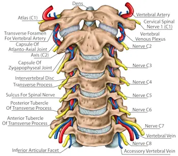
NASA has strict physics requirements for their astronauts as well as a rigorous training process before flight. In comparison, commercial spaceflight has much fewer requirements and a shorter and less strenuous training process. This allows less physically fit civilians to experience the physical toll of spaceflight. Our payload focuses on addressing the possible damage that spaceflight can cause on the spine of the average adult. Since the vertebrae in the neck (c1-c7) weaken the most with age, our payload will focus on that portion of the spine. We will design a brace for the neck in order to mitigate the effect of intense g-forces on the spines of civilian astronauts.
Inspiration
This 3D-Printed Vertebra Is A Huge Step Forward For Medicine (yahoo.com)
Bones
3D print a flexible upper neck / vertebrae segment (c1-c6). Attach it to a similarly scaled 3D printed skull (could have sensors within the skull).
Use special filament
Full-sized Anatomically Correct Articulating Spine by DaveMakesStuff - Thingiverse
Human Skull by MakerBot - Thingiverse
Skin
If we want a more realistic model of the neck/skull, we could incase the bone in a flexible resin that mimics organic tissue. It would involve resin 3d printing a hollow dummy head / neck with RESIONE filament. Software would need to be used to hollow the head. Otherwise we will use a weighted, non-realistic head in light of size-constraints.
https://youtu.be/eely3rxr2to?si=eCa0Uw43PEI_GTwj
STL file head bust for hats and helmets 👤 ・3D printer design to download・Cults (cults3d.com)
Easy Way to Hollow 3D Models in Meshmixer | 3D Printing Tip 2022
The point of any neck brace is to control neck/head mobility in order to reduce load on the vertebrae and other structures
Most astronauts only have to withstand around 3 G during takeoff/landing, but our rocket will reach 14 G… If we want someday to send astronauts in rockets at such high accelerations, we’ll need to understand what happens to their neck vertebrae and how to mitigate any dangerous impacts.
https://www.sciencedirect.com/topics/medicine-and-dentistry/cervical-collar
https://www.webmd.com/pain-management/what-to-know-about-neck-collars
We want to map the pressure distribution or force across a surface area, placing the pressure/force sensor between vertebrae
Goal - Thin, lightweight and accurate Pressure Mapping Sensor or Force sensitive resistors (FSRs).
Article that gives differences between Capacitive, Piezoresistive and Piezoelectric pressure sensors - https://my.avnet.com/abacus/solutions/technologies/sensors/pressure-sensors/core-technologies/capacitive-vs-piezoresistive-vs-piezoelectric/
List of Force Sensors - Force Sensors: Types, Uses, Features and Benefits.
Main Problem of the Silicon based sensors - Large thermal drift because of their high sensitivity to temperature
The Thermal Drift Characteristics of Piezoresistive Pressure Sensor - ScienceDirect. Instead, FlexiForce sensors consist of two layers of polyester substrate; conductive silver is applied on each layer, followed by a layer of pressure-sensitive ink (Evaluation of Flexible Force Sensors for Pressure Monitoring in Treatment of Chronic Venous Disorders - PMC. )
General Problem of Piezoresisitive sensors - Lower accuracy than other sensors
Membrane-like flexible substrate that is printed with two unconnected halves of an interdigitated circuit.
When force is applied to the sensor, its conductive substrate makes contact with printed circuit substrate, allowing electricity to flow from one wire to the other. The amount of electricity that is able to flow within the circuit depends on the pressure exerted on the FSR, as greater pressure brings more of the conductive material in contact with the wires and ups the electrical output in a predictable way, allowing them to detect changes in force as well.
Other types - Inductive Force Sensor, Magnetic Force Sensor
Raspberry Pi Integration
We will be performing the test using an Instron 68TM-50 Universal Testing System that we will be getting access from in the BreakerSpace. We’re most likely going to be performing these tests under the angled load case ( 75 degrees ) to simulate commercial space flight. The use of internal dampeners will possibly eliminate the need to simulate the vibrational load cases, but we could potentially model this kind of behavior.
The relevant specs for the device we’re going to be using are:
Procedure:
Characterizing the data:
Design of the current spine-brace apparatus:
We then created a drawing for how everything would fit in the payload.

11/3/2024 Sunday Work Session:
Neck Design Team: Atharva Shah, William Hazell, Emily Alemán, Michael Vuong
Prototype
Concerns:
Questions for EJ:
Details about material to connect vertebrae to vertebrae:
Purpose: Serve as a cushion modeling the “anulus fibrosis” (intervertebral disk)
Material Options:
Material | Cons | Pros |
Dragon Skin 10 (Needs a degassing process to remove excess bubbles, have to see if we have a vacuum chamber, and this may apply to other materials)
| Have to create subtractive molds for the portion between the bones that are almost completely accurate Shrinkage is possible, depending on the conditions | Superb service range temperatures ( -65°F to +450°F or -53°C to +232°C ) Molds are reusable so its easy to create multiple Skrinkage, though possible, is minimized ( <.001 in. / in. ) |
Soft Flexi Foam | Has no resistance to compression Have to manufacture the soft flexi foam so it accurately reflects the disks | Easy to conform to the vertebrae because of its “foamy” nature |
Silicon - What kind of silicon are we using? I think Dragonskin is also a derivative of silicon | ||
Ecoflex 00-50
Should be Ecoflex 10 or 20 ( available on the website ) if it wants to simulate human tissue | Basically has the same pros/cons as Dragon Skin 10, with the curing process and temperature range Able to simulate the compression of the disks as it retains its shape following compression | |
Ballistic Gel Maybe we can do a combination of Ballistic gel with some other material to simulate the spine | Impact forces Environmental temperatures, the shelf-stable temperature is -10OF - 95 OF | Certified because of extensive use in the medical industry |
Medical-grade plastic (polyethylene) |
Shopping List Materials:
Material | Price per unit | Quantity (# units) | Purpose |
SimuBone Filament Roll | $98 | 1 | 3d printing material for vertebrae - each set of vertebrae uses 20 grams of material (1 spool comes with 750 grams) |
FlexiForce A201 Sensor (8 Pack) https://www.tekscan.com/products-solutions/force-sensors/a201 | $153 | 1 | Measure the compression forces on the spine. |
Raspberry Pi Zero | $25 | 1 | Breadboard with an MPC3008 integrated circuit converts analog signals from force sensors into digital signals that can be read by Raspberry Pi Zero. Raspberry Pi Zero retrieves the data. |
3.7v 18650 cylindrical lithium-ion batteries (2 Pack) | $19.95 | 1 | Powers the system. |
Questions To Ask
Specific questions, concerns:
November 10, 2024
Young’s modulus of intervertebral disk: 30 MPa in the linear elastic regime (that’s actually really high)
Words when presenting: ultimate strength and young’s modulus
Possible Links:
Here is a type of polyurethane foam with roughly the correct density that gives a Young’s modulus in the 10-30 MPa range: https://makerstock.com/collections/foam/products/cnc-and-modeling-foam-rigid-polyurethane-foam-high-density-8lb-ft3
Material | Young Modulus (basically how much it deforms under stress) | Stress-Strain Curve | Ultimate Strength |
Intervertebral Disk | 30 MPA / 0.03 GPa | ||
Rubber (Small Strain) | 10-100 MPa | ||
0.517-62.1 MPa | 0.138 - 165 MPa (tensile strength, ultimate) | ||
150-520 MPa | 10.3-18 MPa (tensile strength, ultimate) | ||
Polyethylene | |||
UHMW Polyethylene (used in actual disc replacements) | 760 MPa | ||
Polyurethane Rubber | 6 MPa | 25 MPa | |
EVA (Ethylene Vinyl Acetate) (this is what shoe soles are made of!) | Pure EVA, 0.3 wt%, 2 wt% stress-strain curve, Young’s modulus, elongation | ||
0.16g/cm^3 polyurethane foam | 15 MPa | ||
Memory Foam (a type of polyurethane foam) | |||
Notes for substitute intervertebral disc material:
Lumbar spine stress-strain curves?
From this article: “Stress–strain characteristic curve of the intervertebral disc at different strain rates. Both the yielding and cracking phenomenon occur at fast and medium loading rates, while only the yielding phenomenon occurs at slow loading rates. (A) The mechanical behavior in L1–2 Segment; (B) The mechanical behavior in L3–4 Segment; (C) The mechanical behavior in L5–6 Segment.”
Note: Material for head weight
Material | Height | Density | Radius | Outer Diameter | Shape | Weight (not accounting for hole) | Price |
Brass | 0.303 to 0.315 lb/in^3 | 1.5 | Cylinder | 3 lb | |||
Stainless Stain | 1.48 in. | 0.27 to 0.29 lb/in^3 | 1.5 in. | 3 in. | Cylinder | 3lb | $86.70 for 6 in |
Low-Carbon Steel |
Vertebrae
https://www.thingiverse.com/thing:4801717
Proportion Head to Vertebrae:
Piece | Real Human | Prototype |
Head Weight | 10 lbs | 3 lbs |
Vertebrae Weight | 44.1 grams | |
Head Weight | Vertebrae Weight | |
Real Human | 10 lbs | 44.1 grams |
Prototype | 3 lbs | 20 grams |
Determination of Proportion:
50% scale for the vertebrae, 30% scale for the head (maximum size for each permissible by dimensions of payload)
11/17/2024 Work Session:
We took off the supports on the initial 3d prints for the spine models. They turned out decent - print quality was low but ball-socket joints work. The spine model could be fully assembled. Next print is being printed so we have another version, but it is using tree supports to see if that is easier. The file was saved and will be printed when someone gets to the metropolis.
Spine model:
Neck model (what surrounds the neck)
Brace
11/24/2024 Work Session:
We took off all the supports for the new 3D printed models of the cervical spine. We have several at the scale of the payload and one model which is 1:1 scale of the actual cervical spine.
We adjusted the stl files for the C1-C7 vertebrae, removing the ball and socket joints; there is now space to adhere the faux intervertebral disks. The new files, at payload scale, can be found in the Teams under the aura-strucc-pl-spine-3 folder.
We refined the CAD of the neck brace, scaling it down so it will fit the cervical spine model. We also implemented a "tongue and groove" approach, allowing each piece of the neck brace to interlock. The foam component of the neck-brace was created in a separate SolidWorks file with the correct material (polyethylene foam).
The CAD was also altered for the head. We realized a traditional cylinder was insufficient to represent the structure of a jaw. The neck brace would have been flush against the flat end of the cylinder, and this rigid connection would have unnaturally stopped all compressive forces on the spine. Instead, the 3in diameter by 1.48in tall head cylinder was given a 0.5 in fillet at its bottom edge. A hole cutout was also made for the rod. Now, the head will fit more naturally against the curvature of the neck brace, and actually be in contact with the supporting foam.
Finally, we received our slide assignments for CDR. We are working on creating a 3D, animated visual representation of the cervical spine/ neck assembly with the final payload in SolidWorks.