Introduction
The design of the autonomous kayaks used by HoverGroup is motivated by our research goals and interests. Briefly summarized, our research aims to provide design and analysis tools for the operation of multiple autonomous vehicles where acoustic communications play a crucial role. There are currently few such tools available that can be applied to acoustic communication where bandwidth is extremely limited and packet losses can be both high and hard to predict or model. Focusing on shallow water or harbor environments, we seek to craft principled solutions that can be tested in the field using real hardware and then evaluated based on their performance.
Of course actual AUVs are expensive to own and difficult to operate, even individually. For this reason we use surface vehicles towing an acoustic modem in place of an AUV. This allows us to easily perform experiments with multiple vehicles while still using actual acoustic communications. The availability of RF communications and GPS based navigation make deployments easier and safer, while these same features can be disabled or ignored to simulate the conditions under which an AUV would operate.
There are several commercially available surface vehicles, such as the Kingfisher by Clearpath Robotics or the SCOUT kayaks made at MIT, but none of the products we explored provided the combination of options we sought. We opted to design and construct our own kayaks instead. This document will discuss the design requirements set by our experiments, the design of the vehicle itself, and field performance. Several iterations were required to reach the current state of the vehicle, and we will not spend much time discussing earlier designs here.
Design Requirements
First and foremost the vehicle must be able to tow an acoustic transducer at a depth of at least three meters. We use the 25kHz WHOI MicroModem as it is recognized as a competitive and up to date progress and our group has close ties with WHOI. The transducer is attached to a heavy towfish that weights down the towing cable and ensures the transducer hangs properly in the water. Speed is also important as the separation between vehicles can often be large and time on the water is limited. We've found that cruising around 2m/s provides a decent compromise between speed and endurance. We also wanted the vehicle to be capable of handling rougher sea conditions such as those found in open harbors.
Our target battery life was on the order of four hours, or a half day's operation. Ideally the batteries should be removable so they can be swapped out quickly when needed and be of a safe chemistry that can charge overnight. We also sought to keep the vehicle's two-man portable and small enough to fit in a rented SUV or uhaul. Operations can be a lot more flexible if neither a truck nor a hoist is required to transport and launch the vehicles.
Finally, we want to keep costs down where possible, but above that keep the vehicles easy to build and maintain. This means using as many COTS parts as possible. If a design element can be simplified or made more reliable by opting for a more expensive part, we will generally do so.
Design
Hull and Locomotion
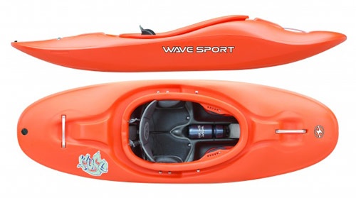
The hull of the vehicle is a Fuse 35 kayak from WaveSport. This is a kid's whitewater kayak, giving it a distinctly different size and shape from the more traditional kayak hull used by others such as the SCOUT. The bottom of the hull is almost completely flat and slopes upwards towards either end. It is wider as well, giving it a decent interior volume despite being just 1.8 meters long. The greater volume to length ratio and hopefully increased stability of a wider hull led us to choose a whitewater kayak over a traditional design.
Thrust is provided by a Minn Kota Riptide series trolling motor rated for 50 lbs of thrust at 12 volts. Several smaller thrusters were tried and did not provide sufficient thrust when towing a modem. Traditionally the thruster is mounted in the stern of the vehicle, but for several reasons we opted to mount the thruster near the bow of the vehicle and mount a skeg astern of it. The flat bottomed hull means that the kayak does not track straight on its own, so a rear mounted thruster would probably make the vehicle very difficult to control and drive in a straight line. The kayaks are also expected to station keep frequently and a bow mounted thruster should provide greater maneuverability and accuracy when doing so. Finally, a bow mounted thruster means the modem can be hung astern of the thruster and the vehicle driven forwards without risk of the propeller hitting the cable.
Tow 80/20 mounting rails are bolted to the bottom of the hull about eight inches apart from one another. Rather than run the whole length of the kayak, these rails run from the front of the flat-bottomed section to around the halfway point in the cockpit. This allows the thruster and several other pieces of hardware to be mounted to the rails in the front, while also freeing up more space in the stern for electronics and batteries.
add overhead picture of kayak here
The mounting and sealing of the thruster shaft and its azimuth servo were the most challenging mechanical aspects of the design and construction. Currently we use the MS530-1 Mega Servo from ServoCity to turn the thruster shaft. The output of the servo is clamped directly to the 1 1/8 inch shaft used by the thruster. Previous designs used a smaller diameter shaft to couple the servo to the thruster shaft, but the smaller circumference made it difficult to prevent slipping. Where the thruster shaft enters the hull a plastic cylinder housing an o-ring and sleeve bearing is bolted directly to the hull. The servo assembly attached to the top of the shaft is mounting to a horizontal plate, which is in turn supported by two more plates connected to the main mounting rails. Instead of holes, slots are used for many of the mounting bolts to allow this upper plate to be adjusted in any direction. This allows us to better align the servo with the shaft seal after the shaft is already installed. Only when the servo is properly aligned and the shaft rotates smoothly do we fully tighten all the securing bolts.
detailed picture of thrsuter mounting, perhaps more description of the shaft seal
Power
The power electronics for the kayak are designed around a constant load of 50 amps. In practice this is higher than what is observed even at max thrust and much higher than the current consumption when traveling at 2m/s. The original kayak design used a number of Lithium Polymer batteries connected in parallel inside the main CPU box. This arrangement provided good energy to weight ratio and simplified wiring, but batteries could not be swapped. LiPo batteries are also notorious for their tendency toward fiery accidents and charging had to be carefully supervised.
Lithium Iron Phosphate (LiFePO4) batteries are now used instead. While not as high as LiPo's, this chemistry still provides an energy density about twice that of a conventional lead acid battery. They are also much more stable and there is almost no risk of explosion or fire, even when overcharged. We use 12.8V 100Ah battery packs purchased from www.batteryspace.com. Tests with a DC load have shown the 100Ah capacity rating to be accurate to within a few amp-hours. We house these batteries inside plastic ammo cans to make them splash proof. Two waterproof connectors provide power and balance connection to the battery.
While these batteries can be charged safely without balancing, the use of a balancer helps improve longevity. Fitting every battery with a built in balancer board would be expensive and difficult to accomplish given the minimal space available in our battery packaging solution. Instead we charge the batteries using FMA Powerlab 6 chargers from ProgressiveRC. These chargers can give a high 40 amp charge rate and a decent 1 amp balance current. Unlike many other chargers, the FMA Powerlab can also be configured to charge a 100Ah battery without running into any safety timer or capacity limit issues. We mount two of these chargers and a 27volt, 40 amp power supply in a pelican case as a mobile charging station.
A RoboteQ LDC1430 motor controller is used to drive the the thruster. Having tried several motor drivers, the LDC1430 is the most reliable and provides several extra features such as voltage monitoring, current sensing, and PWM frequency adjustment. Noise tests with the motor driver and acoustic modem showed a spike at the motor's PWM frequency and another at twice the frequency. By setting a 17kHz PWM frequency (34kHz second spike), we were able to minimize noise near 25kHz as long as the motor is operating at less than 75% thrust. The motor driver is housed inside its own box that connects directly to the batteries and the motor. This same box also provides power and serial communication with the motor driver to the cpu box and connects to the e-stop switch. This design keeps the power electronics isolated from the various electronics inside the CPU box.
Communication
RF communication with the vehicle is provided by two different radios. A 2.4 GHz Bullet M from Ubiquiti provides typical WiFi functionality and bandwidth while increasing range - we usually see good performance out to 600 meters using an omni-directional antenna (~7 dBi) on the vehicle and a sector antenna on shore (~12 dBi). The Bullets are also easy to configure and weatherproof so they can be installed in the kayak without any sort of housing. Power and data are provided together via ethernet.
More recently, a longer range communication option has been added in the form of a Freewave FGR2-PE 900 MHz ethernet radio. These radios are lower bandwidth (~115Kbps shared among all active radios) but are much longer range (many miles theoretically, still testing). They enable us to more easily perform experiments in open water that test the range of the acoustic communications, which could be several kilometers. When in use, the freewave radios are installed in their own box much like the motor driver along with an ethernet switch and power switching board. Due to the small size of the kayak, the two antennas cannot be separated enough to avoid interference. Instead, only one radio can be powered on at a time on the kayak while the ethernet switch will automatically select the functioning radio to pass packets to and from the shore.
In addition to the data communication channels, an RC controller can also be used to drive the kayak over short ranges. The details of this link will be discussed further in the next section.
Sensors and Control
The key sensors for navigation are the compass and GPS. The compass is an OS5000 model from Ocean Server, which uses a serial interface and is fully tilt compensated. There are cheaper options for tilt compensated compasses, but the serial interface on the OS5000 is easy to work with and calibrated the compass is a simple process. Horizontal and vertical calibration can also be done independently, which is important because the vertical calibration can be difficult with the compass mounted in the kayak. Previous designs mounted the compass in the CPU box along with most of the other electronics (excluding the motor driver and freewave), but the compass was later moved to its own smaller enclosure mounted in the bow. This was done to separate the compass as much as possible from any noise sources. The compass enclosure is mounted at an angle, but the compass itself is mounted such that it is level when installed in the vehicle. This allows us to perform a horizontal calibration on the dock without removing the compass from the vehicle.
Consistent GPS performance is important when analyzing results of experiments.