This project is now in cold storage. As of 2014-06-23 Erik Ersland has sent all needed info to the Harvard team (that traitor) since they are doing something that they want to change colors.
If anyone wants to send someone this project or is trying to figure out what the heck this is, use(read) an email like this and attach "shift register design, view this first.pptx" and "Genetic shift register function.pptx" from the attachments to this page. The power points should contain all the information you need.
The old log of meeting notes follows, as transcribed by Jiaqi. All of the old documents are attached to this page
Members: (Add Your Name if interest post cutoff)
Erik Ersland
Shinjini Saha
Jiaqi Xie
Alex Leffell
======================================================================================================
Just setting a page down to see what you guys have and to share resources.
Linked list circuit
if you add a timer to produce the advance signal, it will be a clock
This uses only cas9 repressors and a small molecule signal to handle states.
Key:
-> constitutively active promoter
n:binding site for cas-9 repressor for nth node, allows transcription without cas9
n':binding site for cas-9 repressor for nth node, allows transcription without cas9
A: (code for advance) some system so that A must be present for transcription
(n) and (n'): codes for guide rna that binds to n or n' to stop transcription there
payload: the reporter for a node, each node will have a different one so you can see state, each node will probably have a different fluorescent protein.
, breaks up units of transcription regulators and gene expression, each unit between commas is a promoter, the appropriate regulators, and the expressed molecule
each line is a node
circuit of nodes (there isn't supposed to be a cross out, I don't know why its there)
->0'(1),0 payload,>0(3'),>0(3),->A0(0')
->1'(2),1 payload,>1(0'),>1(0),->A1(1')
->2'(3),2 payload,>2(1'),>2(1),->A2(2')
->3'(0),3 payload,>3(2'),>3(2),->A3(3')
explanation of components (same comma convention):
normally blocks next node,payload is on when node active, previous nodes blocking blocked when node active so a node activates itself, node blocks previous node for state transitions, node blocks blocking of next node when active and activator present which causes next node to turn on also for state transitions.
initial state: [(0),(1),(2),(3)] present (blocking active behaviour)
all nodes are now inactive and [(0),(1),(2),(3)] produced
state change: (0') introduced
(1) stops being produced by node 0
1 becomes active
1 payload expressed
(0') produced, reinforcing 1 on state
[(0),(2),(3),(0')] present
state is now 1 and only one active
state change: (A) introduced ,now [(0),(2),(3),(0'),(A)] present
0,2,3 ignore it because normal suppressors active
on node 1, (1') is produced since (1) not present and (A) present ,now [(0),(2),(3),(0'),(A),(1')] present
(2) not produced any more, now [(0),(3),(0'),(1')] present
(you need to remove (A) before 2 fully active since it would cause another state transition, may also get around this by using two different (A)'s and alternating between them as well since the one that causes 1 to 2 would note cause 2 to 3, other mechanisms probably exist as well)
2 becomes active
2 payload expressed
(1') produced, enforcing 2 on state
(1) produced, deactivating 1 (the intermediate state of 1 and 2 both active automatically proceeds forwards to just 2 being active)
(0') not produced
now [(0),(1),(3),(1')] present
state is now 2 and only 2 active
future state changes: each addition of (A) will move state forward one slot
for an active stage n, (A) causes n+1 to be active, so both n and n+1 are active, then n+1 causes n to be inactive, so n+1 is the only active state.
all nodes are inactivated by the previous node except the active one.
======================================================================================================
14 Feb 9
Applications:
Time progression, biological clock.
Any multi-step chemical/biological process moderated by a single organism.Beer brewing.
Ethanol/Biofuel production.
Drugs/Enzyme production.
Chemical processes with steps that would normally interfere with one another moderated locally.
Safety precaution, self-termination.
Biological CS circuits. Large AND and OR Gates
Add back command to create Turing Machine.
------------------------------------------------------------------------------------------------------------------------------------------------------------------------------------
Implementation:
Cas9, Guide RNA for repression.
mRNA sensing repression.
======================================================================================================
14 Feb 12
Updated Powerpoint with improved sprites and arrow pushing. V2
======================================================================================================
14 Feb 13
Brainstorming session.
Forgot some repression arrows. Message was clear enough such that no one cared. Will fix if not lazy. -JX
Cell that allows for post processing.Yeast that has the capability to creating a variety of beer.
======================================================================================================
14 Feb 20
Victory.
Our brave soldiers have triumphed over the forces of ??? in the battle of the first cutoff.
Todo: Make a mailing list and post on wiki and igem-2014.
Coordinate meeting times for preliminary experiments and circuit design.
Human(e) practices?
Monsanto?
Control? Termination? Transfer?
- JX
======================================================================================================
14 Feb 27
Pre-meeting Pow Wow:
Anschluss failed. 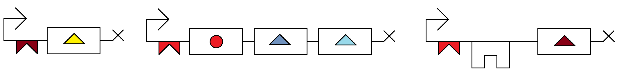
Signalling unit.
Middle segment can be one piece or separate, need testing.
Activating small molecule:
rtTA (Tet-ON) system:
http://www.tetsystems.com/science-technology/scientific-figures/#c22 (first diagram to the right.)
------------------------------------------------------------------------------------------------------------------------------------------------------------------------------------
Testing:
Primary Chassis Considered: Yeast
Middle segment can be one piece or separate, optimization?
Precise mechanism for the AND of the last part needs testing.
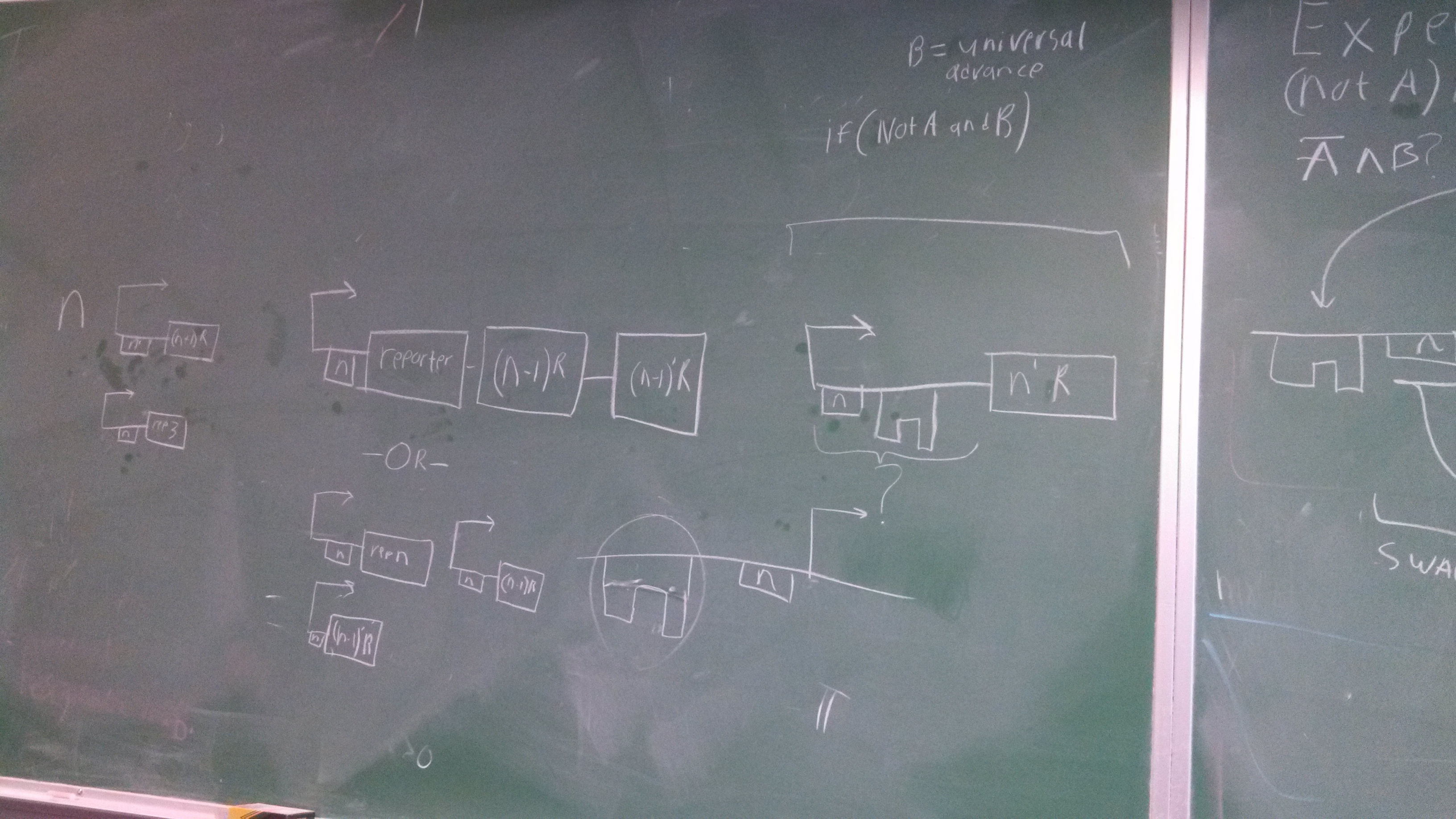
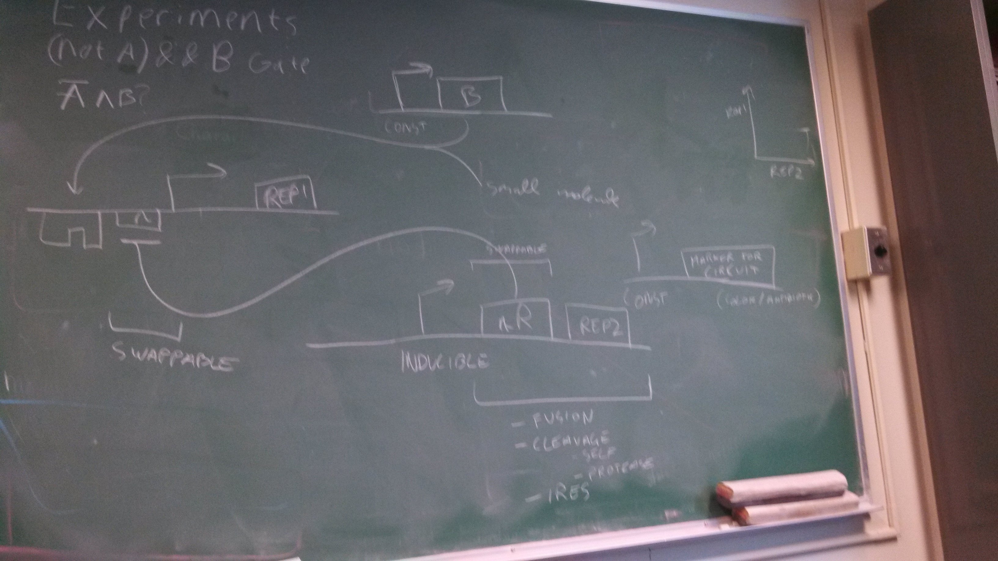
(NOT A) && B Gate
Degradation rate of Repressors, measured and controlled. State change time sensitive.
Look up circuitry. 6.004 ocw materials.
Propagation times and state thresholds (determined by cooperativity and binding kinetics, and etc. ).
------------------------------------------------------------------------------------------------------------------------------------------------------------------------------------
Motivation:
Technological Advance.
It's big.
Large system testing. (Lot's of TAL_Rs)
State based combinational system.
Memory System.
Beer.
Drugs.
Vat Production.
------------------------------------------------------------------------------------------------------------------------------------------------------------------------------------ 
------------------------------------------------------------------------------------------------------------------------------------------------------------------------------------
From Ron:
======================================================================================================
14 Mar 6
Annexation!
Alzheimer has annexed XNA! The international community will not stand for this!
Alzheimer has annexed Turing Machines! The international community will not stand for this!
------------------------------------------------------------------------------------------------------------------------------------------------------------------------------------
Human Practices Pre-Brainstorming:
#Safety Mechanism#
Any safety mechanism/self termination system will be heavily selected against.
Production of toxins that kill neighboring cells. Cells that fail to undergo suicide will be eliminated by their more competent neighbors.
Transfer crucial genes into shift register. The deactivation of the register and it's associated gene will lead to cell death.
Prevent logic failures by making every state after a critical threshold program for death.
Make the forward signal a signal from cell division, advancing the state with every generation of cell division.
#Vaccine#
Immunizations can have their effect maximized by 1: having a larger imune response (duration and quantity of antgen), 2: have multiple antigens for a given disease, and 3: have only one antigen at a time (apparently if you have too many antigen, the immune system only deals with a few). Our project is perfect for this. I read somewhere about implanting a colony of microbes in a physical barrier that prevented cells from getting through but not molecules. We could have a colony of yeast (or whatever is the easiest to kill should it escape) that produces a large set of antigens over a long time
period, having the effect of many successive shots over a long period of time, then self destruct when its done. On top of this, any drug treatment that has multiple stages of therapy use this to try and reduce the amount of procedures and drugs needed.
Counting circuit. One injection/implantation. Over time, the implanted colony cycles through the antibodies, increasing effectiveness of immunization by exposing the body to only one antigen at a time.
------------------------------------------------------------------------------------------------------------------------------------------------------------------------------------
Brainstorming:
Logic Gates/better visuals needed. Get someone on it in the near future.
Need alternating advance molecules, or a shift register to alternate so that machine doesn't advance too many states.
Need to look into biological shift registers, and their ability to resist changing states multiple times in the presence of the signal.
iGEM meet:
Ron's ideas:
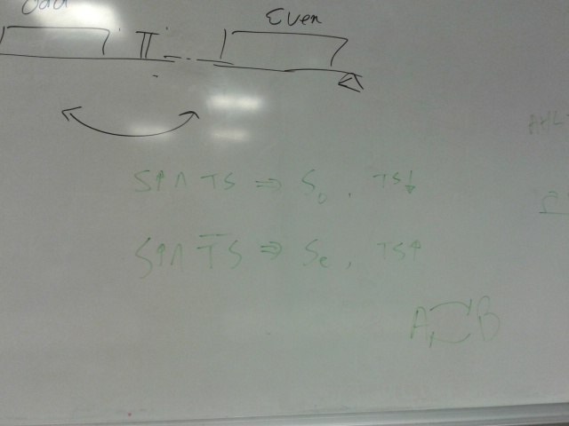
Pulse generator switching on S_even and S_odd alternately. Need to look into how this could be achieved, possibly in a simpler way than the toggle switch.
======================================================================================================
14 Mar 13
New Member!
@#$! Yeah!
======================================================================================================
14 Mar 20
Where is in the world is Carm...
Modeling talk I'm not quite sure of. PROGRESS!
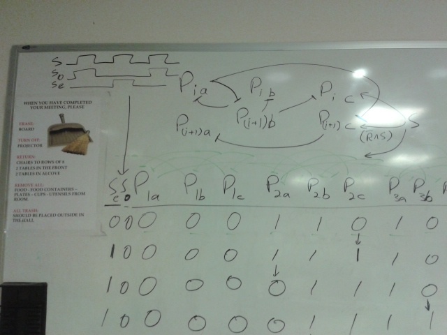
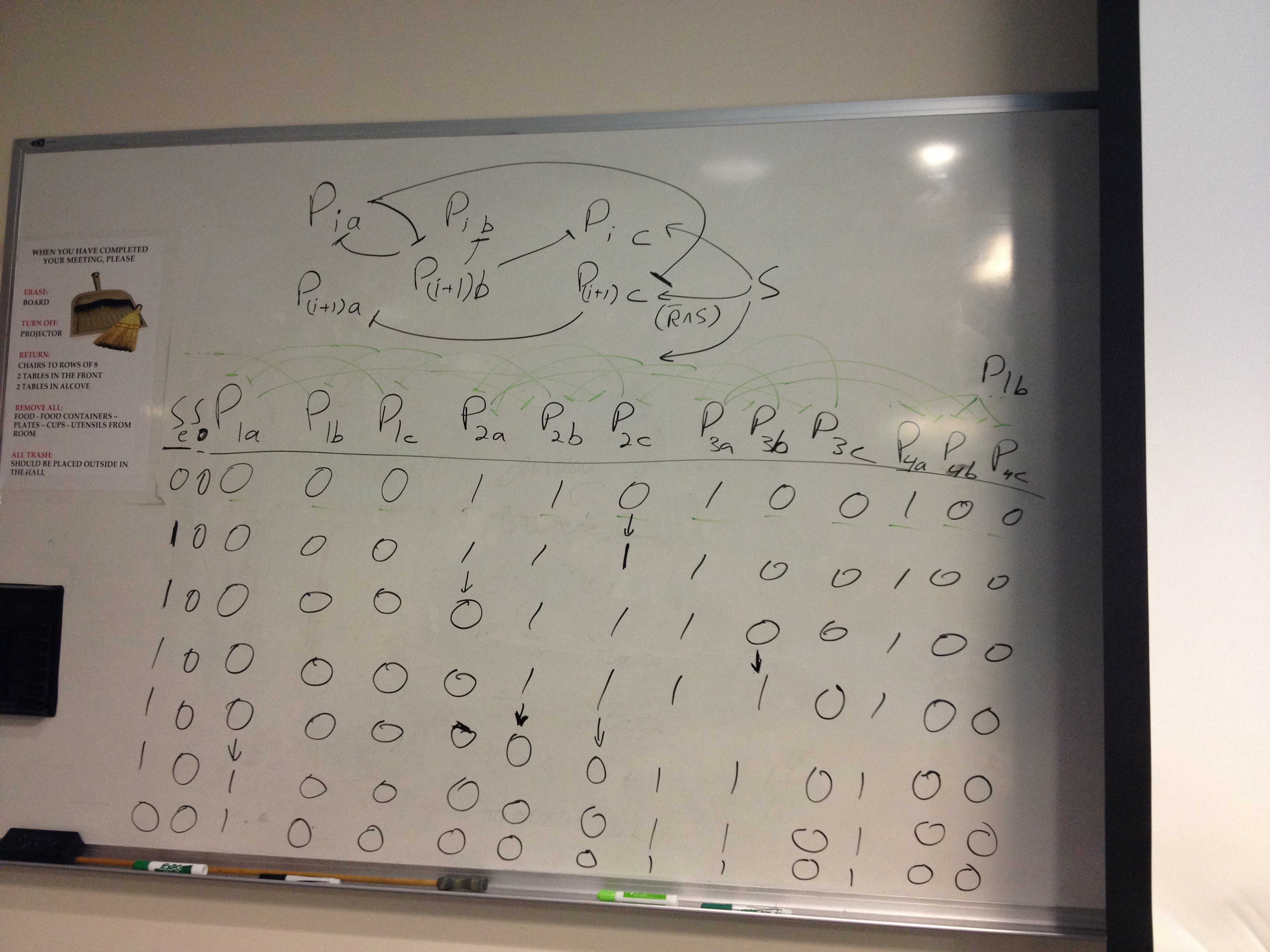
Debugging Galore!
======================================================================================================
14 Apr 10
You wish your circuit diagrams look this good....

Who am I kidding.
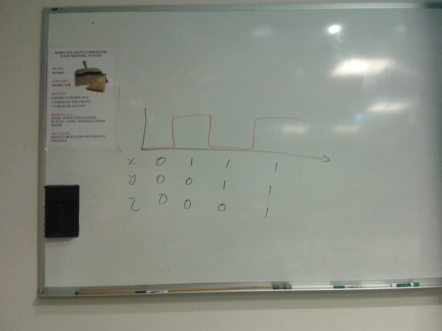
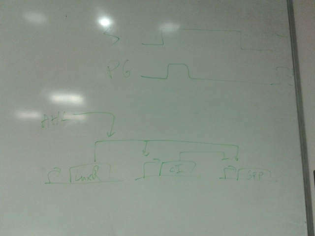
The top part represents a toggle switch that filters the step signal to prevent an oscillation. The four repeating units represent the primary design of the current project.
Bright green represent active paths and dark green represent inactive paths.
======================================================================================================
2014-Apr-22
Allocation of responsibilities.
How does current project fit in with Alzheimer's project?
Implementation? Human practices?
Transition to dosage control? Titration project? Combine with Alzheimer.
- Make friends with Alzheimer's.
- Interim Technical Report on Shift Register.
- Define processing component for Alzheimer's.
- Cold storage. Clean up the wiki.
======================================================================================================