Warning! This analysis has been indicted in the failure of Hermes Flight 2!
Overview
This is a first pass mechanical sizing of fin can structural requirements. It makes a lot of conservative assumptions.
- The fin core, fin roots, and fin fillets have no stiffness and bare no load
- The carbon fiber plies are .010 in thick
- The composite matrix has no compressive strength
Load Estimation
The fin's weakest axis is reacting moments around the root of the fin. To size the carbon fiber tip to tip layup for this case we need to estimate the moment around the root of the fin. From aerodynamics the force on the fin is
| LaTeX Math Block |
|---|
|
F_{fin} = \frac{1}{2} C_L \rho V^2 |
Integrating this over the length of the fin we can obtain the moment
| LaTeX Math Block |
|---|
|
M_{fin} = \frac{1}{2} C_L \rho V^2 \int_{0}^{H}c r dr |
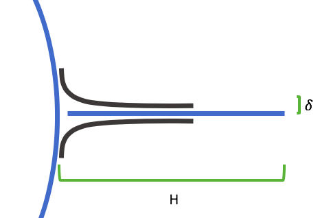
c = chord length at fin height r
H = height of fin
Structural Calculations
From compatibility we can write the following
| LaTeX Math Block |
|---|
|
M = F*\delta = \sigma*\delta*A |
| LaTeX Math Block |
|---|
|
\sigma = \frac{M}{\delta*A} |
Now knowing
we can calculate the number of plies of carbon fiber we need at a give factor of safety to meet load cases.