...
One of the main challenges with using a pintle injector for a nitrous-ipa combo is spray angle. A lower spray angle is desirable because it means the mixed propellant has to travel further to reach the wall, and so can disperse more. However, when using nitrous-ipa as propellants, a high mixture ratio is often used. This means that the nitrous will have a lot more momentum than the ipa, and since the pintle is ox-centered (there is basically no way to manifold the regen cooling to the center of the injector to have it be fuel centered) the spray angle will be exceedingly high. However, we intend on drilling the pintle holes at an angle to enforce a lower spray angle.
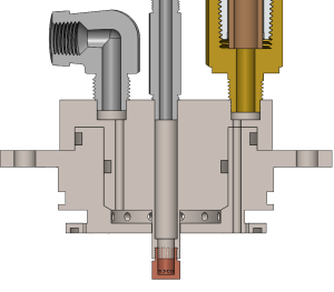
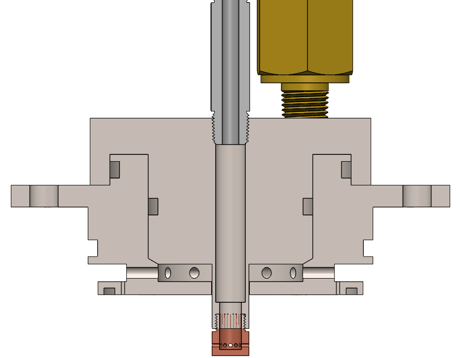
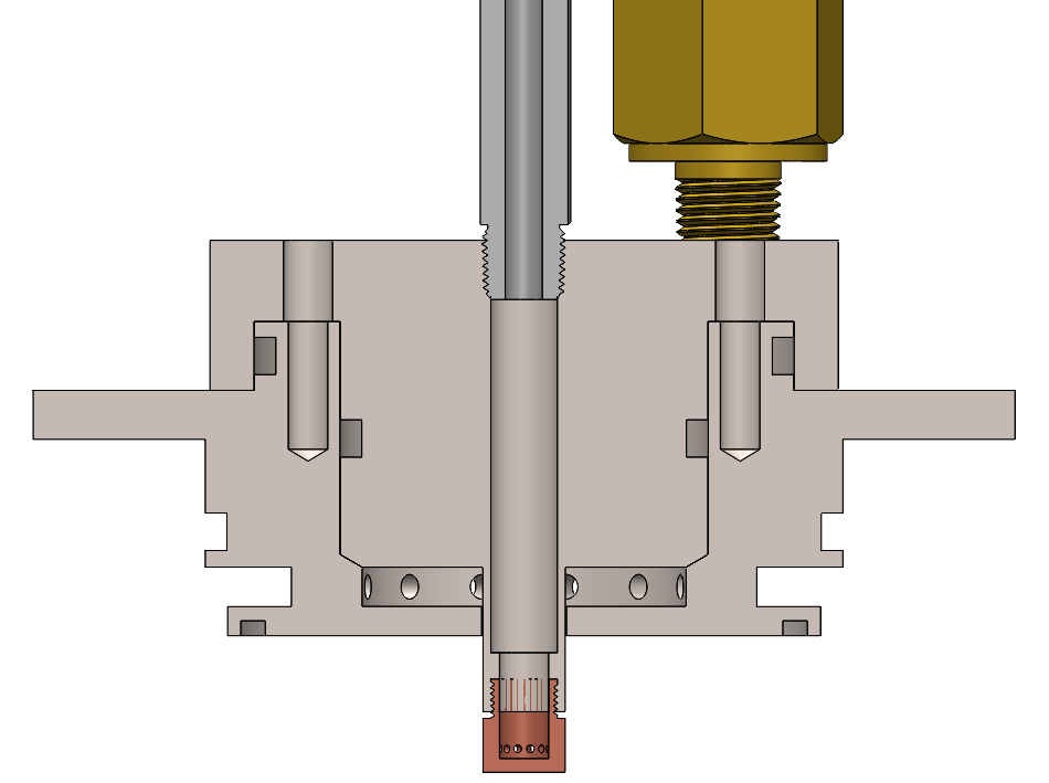


This is the current iteration of the pintle injector, with some dimensions (i.e. number of film cooling holes or number of flange bolts) not calculated yet. Also, the nitrous orifices are not angled yet. However, the final design will most likely closely resemble this, as it is machinable and contains no interpropellant seals.
...
- Radial holes in the baseplate are actually good because they reduce the flow velocity into the annulus. Just make the total area of the holes ~4 times the area of the annulus to make the velocity lowest.
- The pintle should usually be tapered and also sit on a tapered baseplate so that it's centered. If it isn't resting on a slanted surface, then the flange bolts will wobble, which will cause the pintle to translate left and right slightly, which will ruin your annular gap flow.
- Make the tip out of copper and the rest out of steel or aluminum if you think it'll survive so that if the tip gets scorched slightly after a burn you won't have to make the whole center body again.
- For injector face materials with low thermal conductivity like steel, a good practice is to regeneratively cool the face exposed to the combustion chamber gases, which can only be done if that thickness is very low. However, since this engine is operating at a mixture ratio far from stoichiometric, and since the pintle will create recirculation regions below the face, I've chosen to not make the thickness of that part low. The thickness will ultimately be determined by running FEA.
- In pintle injector design, the reason why there's a taper in the centerbody is so it can sit against a similar taper on the baseplate. Since the bolts connecting the centerbody to the baseplate are axial, the centerbody can translate horizontally when the engine is running due to vibrations. Although this may seem counterintuitive because the centerbody sits between two walls in the baseplate, remember that these walls aren't touching as there needs to be a diameteral clearance for the O-ring. Having a taper, however, eliminates this issue.
- If you're concerned about angle tolerances here, know that angularity doesn't matter so long as it's close enough. Surface runout does, but typically this is a small fraction of the total assembly runout. A taper fit essentially trades a slightly worse runout on the piloting surfaces for much better (0) assembly runout, whereas two cylindrical surfaces with a clearance fit can have a slightly better runout on the surfaces but the clearance on assembly creates a significant assembly runout. At the end of the day the concentricity error won't be such a big deal but considering a tapered fit is much more tolerant to assembly runout without being that much harder to make, and that pintles already suffer from flow maldistribution without even considering concentricity, it's probably the way to go.
- If using a taper-taper design, however, it is discouraged to use face seals for the centerbody-baseplate connection. It is unlikely that you can tolerance the part well enough to have sufficient O-ring compression and full contact with the tapers. We had this issue previously, and fixed it by making all seals between the baseplate and centerbody radial seals.
- As said by CommanderSpork (halfcat god) about nonhypergolic pintle injectors: "Pintles are fundamentally shear injectors. They are not supposed to be impingers. The whole idea is to have a thin film of fuel passing by high-mass flow streams of oxidizer. As fuel passes between these big jets of ox, it is sheared off and carried away, getting much better mixing than impingement. It then slams into the wall, creating high turbulence and the well-known recirculating regions which help improve residence time. The blockage ratio parameter, which is the amount of circumference occupied by oxidizer slot frontal area, is important because it describes the relative amount of area for that shear mixing to happen. It's a highly empirical science; too much blockage ratio and it becomes more impinger, with not a lot of slot length for shear to happen. Too little blockage ratio and, while you get plenty of slot length to shear fuel, the fuel may be too far away from the streams to effectively shear. Test campaigns and CFD go into figuring this stuff out on an engine-by-engine basis, though for injectors of similar design parameters you can scale it up. The primary slots do all the heavy lifting in efficiency; my understanding is that secondaries only exist to catch any fuel that made it past, and that's why they're usually very small. The wall temperature also has a non-trivial effect on pintle efficiency. Consider that the Lunar Module Descent Engine was ablative (and hypergolic) and what effect that might have." This statement motivated us to switch from radial holes on the pintle tip to radial slots. They are currently 10 thou in thickness.
Questions for future iterations:
...