Return to Fluids Group Research
Driving Nozzle Performance
(Below are important performance values for our engine. We want to design the geometry of our engine to optimize these values).
Isp - specific impulse
Specific impulse is a quantity effectively measuring the efficiency of an engine through the relation of thrust and mass flow rate; from the equation, this efficiency may be viewed as the impulse obtained per unit mass of propellant.

F=thrust
ṁ=mass flow rate
g0=9.8 m/s2
ṁcc=combustion chamber mass flow rate
Ve=exit velocity
Ae=exit area
Pe=exit pressure
Pa=ambient pressure
Assuming a higher efficiency is more desirable, our goal is to maximize our Isp, thus maximizing efficiency. In the case of our engine, we may make a few simplifications in our model of Isp. Because our nozzle is matched, we may eliminate the 2nd term of the thrust equation thus allowing us to also eliminate the mass flow term under the key assumption that all propellants flow through the combustion chamber. This leaves us with the following model:
Ve=exit velocity
g0=9.8 m/s2
It is important to note the discrepancy between calculated Isp values and those achieved in practice. While our model assumes ideal combustion and lossless flow, these factors and others account for the lower efficiency observed in practice compared to calculations.
...
C* is related to the chemical properties of the fuel and oxidizer within the combustion chamber (different combinations of fuel and oxidizer will affect its value). The most typical way to increase C* with a given fuel and oxidizer is to increase the combustion temperature, which is done by altering the ratio of fuel and oxidizer used. However, other considerations taken into account such as max temperature for the combustion chamber wall material force non-ideal ratios to be used in practice. C* can be found both theoretically and experimentally with the equations below.

C*=characteristic velocity
R=gas constant
gc=acceleration due to gravity
Tc=combustion chamber temperature
𝛾=specific heat ratio of propellant mixture

C*=characteristic velocity
At=throat area
Pc=chamber pressure
gc=acceleration due to gravity
ṁ=mass flow rate (of gas)
Cf - thrust coefficient
Cf is a measure of the thrust amplification by the engine’s nozzle, essentially being a measure of how efficient the nozzle is. The nozzle expands the exhaust gas to lower pressures and higher velocities, increasing thrust, and Cf is a measure of how well it does that.
Cf depends on the chemical characteristics of the fuel and oxidizer, the expansion ratio of the nozzle exit area and throat area, as well as the different pressures within and outside of the engine. The expansion ratio alters the ratio of exit to chamber pressure, thus changing Cf itself. To have the best possible Cf, an engine should have a very high chamber pressure which the nozzle turns into a low exit pressure matching the ambient pressure around the nozzle.

Cf=thrust coefficient
𝛾=specific heat ratio of propellant mixture
Pe=exit pressure
Pc=chamber pressure
𝜺=expansion ratio (exit area/throat area)
Pa=ambient pressure
Combustion Chamber Geometry
...
The combustion chamber functions most notably as a point for propellant mixture and combustion, ideally at a high efficiency. Propellant stay time is the time required of propellants within the combustion chamber for complete mixing and combustion and is reliant on many factors. These factors include propellant combination, the state of injected propellants (liquid, gas), chamber geometry, initial conditions from injector design, and rate-limiting factors. Propellant stay time is related to chamber volume by the following equation:
Vc=chamber volume
Wtc=propellant mass flow rate
V=average specific volume
ts=propellant stay time
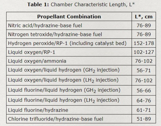
L* - Characteristic Length
...
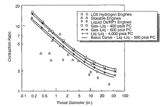
The contraction ratio is the ratio of the cylindrical cross-sectional area of the chamber to the cross-sectional area of the throat of the nozzle. Larger engines typically have a low contraction ratio with a longer chamber length, and smaller engines typically have a larger contraction ratio with a smaller chamber length to have a large enough L* for complete fuel combustion. Along with L*, the contraction ratio governs how wide vs. how long the chamber will be. If the ratio is too small, the chamber might be needlessly long while increasing weight and cost, and if the ratio is too big the chamber might be either impractically wide or not allow for adequate gas flow.
Engine Design Process
After considering the parameters outlined above, the engine design process may begin. This process focuses heavily on engine geometry and dimensions including the comparison of our engine to others of similar size and performance and weighing benefits of certain design choices over others guided by established empirical data.
The design process must begin by making initial design choices as to derive other parameters of the engine. While this may appear to require experimentation to establish such parameters, empirical data from other engines is quite useful in doing so in a much more practical fashion. In our design these initial parameters include L*, contraction ratio, contraction angle, and divergent angle all of which will be chosen from empirical data.
Step 1 Derive Chamber Volume from L*
L* is a function of many propellant-specific factors. As our propellant choices are LOX and RP-1, we begin by choosing an L* value from the table below:
After choosing an L* within the desired range through previously listed considerations, we may use the following equation to derive a chamber volume:

Vc=chamber volume
At=throat area
We have now defined a chamber volume as a product of our chosen L* and throat area, allowing us to further define our chamber geometry through the following steps.
Step 2 Calculate Converging Section Parameters
The calculation of converging section parameters requires two design choices, the contraction ratio and the contraction angle, both of which are chosen from empirical data:
Contraction Ratio
Contraction Angle
“The half-angle of the nozzle convergent cone section can range from 20 to 45 deg.” (Huzel and Huang 1992)
With a contraction ratio and contraction angle defined, we may use the follow equation to solve for the converging chamber section length:

Rt=throat radius
ε=contraction ratio
R=arc radius=1.5*Rt
a=𝛼=contraction angle
Using the converging section length and the formula for the volume of a truncated cone, we may now derive the volume of the converging section of the chamber:
V=converging section volume
r1=chamber radius
r2=throat radius
h=converging section length
The chamber radius is derived from the contraction ratio equation shown below:

εc=contraction ratio
Ac=chamber cross-sectional area
At=throat cross-sectional area
Step 3 Extract Cylindrical Lengths
We would now like to extract both the cylindrical length and the complete length of the chamber. As we have obtained all necessary parameters for such derivations, the following calculations are possible through simple algebra and geometry.
Using the total chamber volume and the converging section volume, calculating the cylindrical volume is simply the difference between the two. Subsequently the cylindrical length is also easily calculated geometrically using the cylindrical volume and chamber radius. This leaves the complete chamber length as the sum of the cylindrical length and the converging section length.
Step 4 Define Chamber Surface Area
As outlined prior, the surface area of the chamber is an important consideration in our design regarding thermal and structural parameters. Using the equation below will yield a surface area:
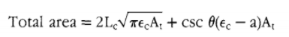
Lc=chamber length
εc=contraction ratio
At=throat cross-sectional area
θ=contraction angle
a=1 (approximation)
This concludes the calculation of major parameters within the combustion chamber.
Step 5 Calculate Diverging Section Length
The final aspect of engine design is the nozzle (diverging section), specifically the length. This may be calculated using the same equation as converging length. As before this calculation requires a design choice, in this case, the divergent angle.
“The divergent cone half-angle 𝛼 varies from approximately 12 to 18 deg.” (Huzel and Huang 1992)
Rt=throat radius
ε=contraction ratio
R=arc radius=1.5*Rt
a=𝛼=divergent angle