Unless stated otherwise, connector positions are described as looking at the outside of the box.
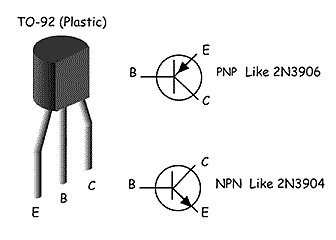
source: http://www.reprise.com/host/circuits/transistor_pinouts.asp
Motor Driver Box:
| Section |
|---|
| Column |
|---|
| LED Control:DOUT1 - pin1 on motor driver DB15 connector
+5V taken from LED driver 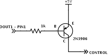 External connector shared with e-stop:
Bottom right - LED +
Bottom left - LED - |
| Column |
|---|
| Motor Driver:Roboteq I/O connector:
1 - DOUT1 - see led control above
2 - TX - green - top left on cpu connector
3 - rx - blue - top right on cpu connector
4 - DIN1 - e-stop - top right on e-stop connector
13 - gnd - power switch led gnd
14 - 5v - power switch led + and e-stop top left CPU Box Connector:
top left - green - roboteq tx - roboteq I/O pin 2
top right - blue - roboteq rx - roboteq I/O pin 3
bottom left - power ground
bottom right - power vbatt Power Switch Wiring:
C1 - power control
NO - vbatt
NC - ground
LED+ - roboteq i/o pin 14 (5v)
LED- - roboteq i/o pin 13 (gnd) |
main power plugs put positive on the right, ground on the left
batteries use the opposite (positive on left, ground on right)
batteries also use center pin for balance ground, then highest voltage top right decreasing clockwise (lowest/first cell top left) |
CPU Box:
| Section |
|---|
Arduino Shield <-> Power Board| Column |
|---|
| | line | Power Board Label | Arduino Label | Arduino Pin |
|---|
Radio power control | Sense | unwired | A4 | Servo power control | 6v | RAUX | A3 | Vbat control | Not labeled | unwired | A2 | 12v control | 12v | R12 | A1 | Servo pwm | Servo | SRVO | A0 | gnd | Gnd | GND | GND | +5 | vin | 5v | 5v | power reset | Not labeled | VBAT | 12 |
radio power control is no longer used as of radio box redesign in january 2015 |
|
| Section |
|---|
Modifications and Bodges:| Column |
|---|
| Power Board: - Vbat control (unlabeled between 12v and 6v) must be wired to pin 1 of its optorelay (immediately below the left main power connector)
- Radio power control must be manually wired to a 2-pin KK connector (along with 5V) in the proto area
- Optorelay for 6v control must be double up, and its associated resistor (vertical and to the left) halved to ~300 ohms
Arduino Shield: - Radio power control and VBat control must be manually wired (see tables above)
- 12v control line transistor can be bypassed
- motor driver is wired to serial uart 2
- gumstix is wired to serial uart 1
- tmp102 temp sensor resides on i2c bus
- sbus wired to uart3
- wiznet wired to default uart (shared with usb)
|
| Column |
|---|
| Arduino Serial Details: 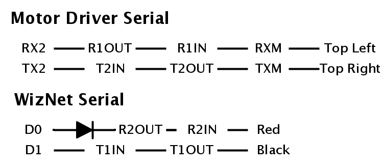
wiznet serial now comes in on ethernet spares:
brown to R2in
striped brown to T1out |
|
| Section |
|---|
Self Power Reset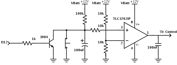
on kestrel this has been modified as follows to prevent the positive input from hitting the positive rail. 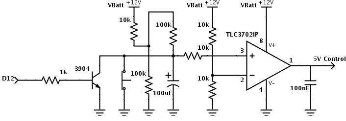
|
| Section |
|---|
3.3V power for radio box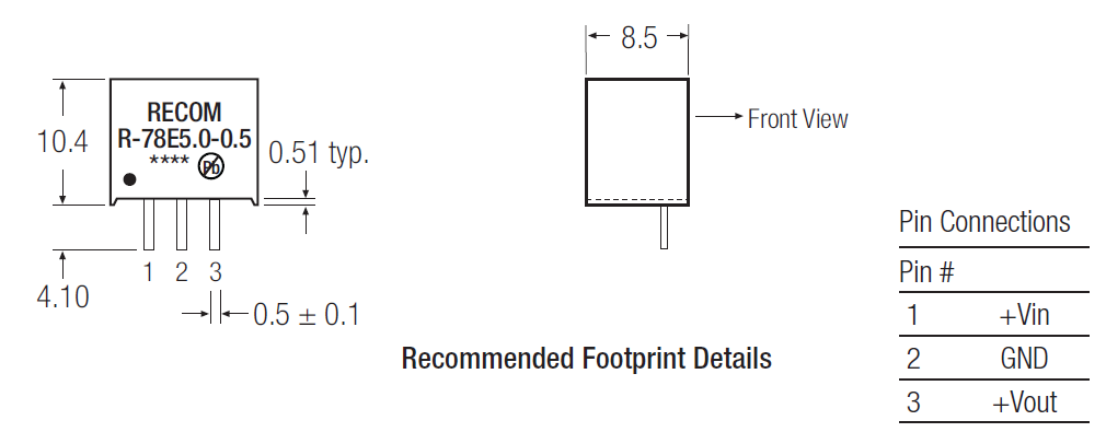
|
| Section |
|---|
External Connectors on cpu box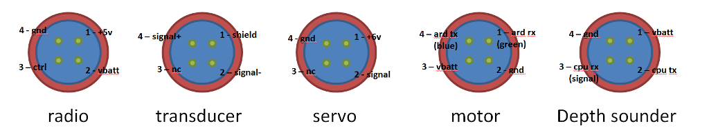
new radio boxes now use 3.3volts on the control pin
radio plug on radio box is mirrored (left right) from the radio plug shown above |
| Section |
|---|
FTID USB-COM232-PLUS42 - rxd
3 - txd
5 - gnd modem port A
db9 pin 2 <-> top right
db9 pin 3 <-> bottom middle
db9 pin 5 <-> bottom left freewave port B
db9 pin 2 <-> solid blue
db9 pin 3 <-> striped blue external/altimeter port C
db9 pin 2 <-> bottom left (viewed from outside)
db9 pin 3 <-> bottom right |
| Section |
|---|
| Column |
|---|
| Tritech Depth Sounder: - Draws approximately 110mA at 12v
- 3 pin impulse connector with pin 1 higher than the others and closer to pin 2 than pin 3
- 1 - gnd
- 2 - signal (rs232, 9600 baud)
- 3 - power (vbatt ok, 10.5-20v)
Cruzpro Depth Sounders: - red - power
- shield - gnd
- green - signal
- white - unused
|
|
Radio Box
| Section |
|---|
RJ45 reference:
In 100BaseT link only orange and green pairs are used, blue and brown are spare. External ConnectorSee cpu section above Wiznet (WIZ108R)Make sure serial debug mode is turned off in configuration tool 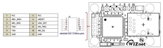
Freewave:RS485 pinouts:
D+ short pins 5 and 6
D- short pins 7 and 8
gnd on pin 4 RS232 pinouts:
pin 4 gnd
pin 5 RX
pin 6 TX COM1 used for RS485 COM2 used for RS232
pin 5 - rx - striped blue
pin 6 - tx - solid blue Moxa rs232/rs485 converter (TCC-80)db9 rs232 side uses
tx - 2 - brown
rx - 3 - striped brown rs485 side must have ground connected
power plug must have ground and +5v moxa dip switches: 1 and 2 on (rs485 two wire), 3 off (no termination) Bullet PoEPOE on spares uses
blue and striped blue for DC +
brown and striped brown for DC - Overall: |
Payload Computer
Positive power bottom left, ground bottom right