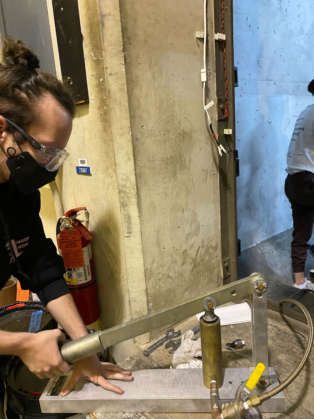
Hydrostatic Testing
Hydrostatic testing is when we pressurize our motor case with water to test the seal of our hardware at high psi. Hydrostatic testing allows us to determine the pressure thresholds of our design and give us a chance to calibrate any sensors or Data Acquisition Systems (DAQ) before static fires.
Hydrostatic Setup:
- Check motor
- make sure no phenolic or graphite parts are in motor
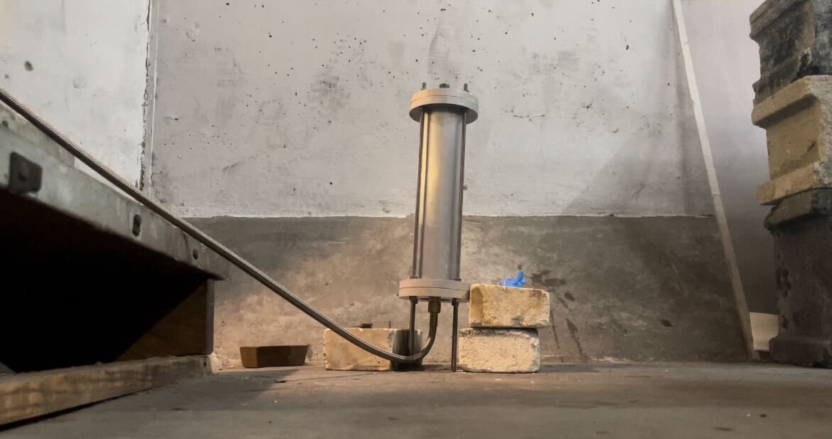
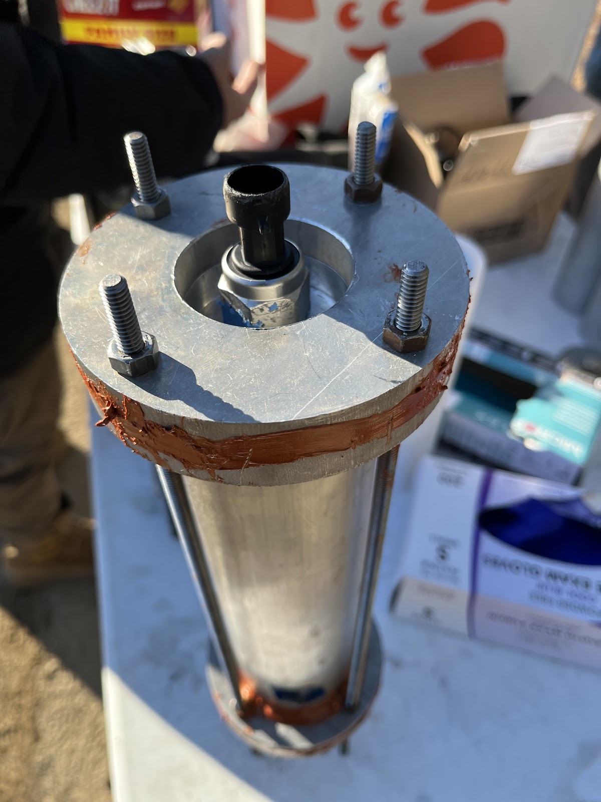
- check installation of hydrostatic cap
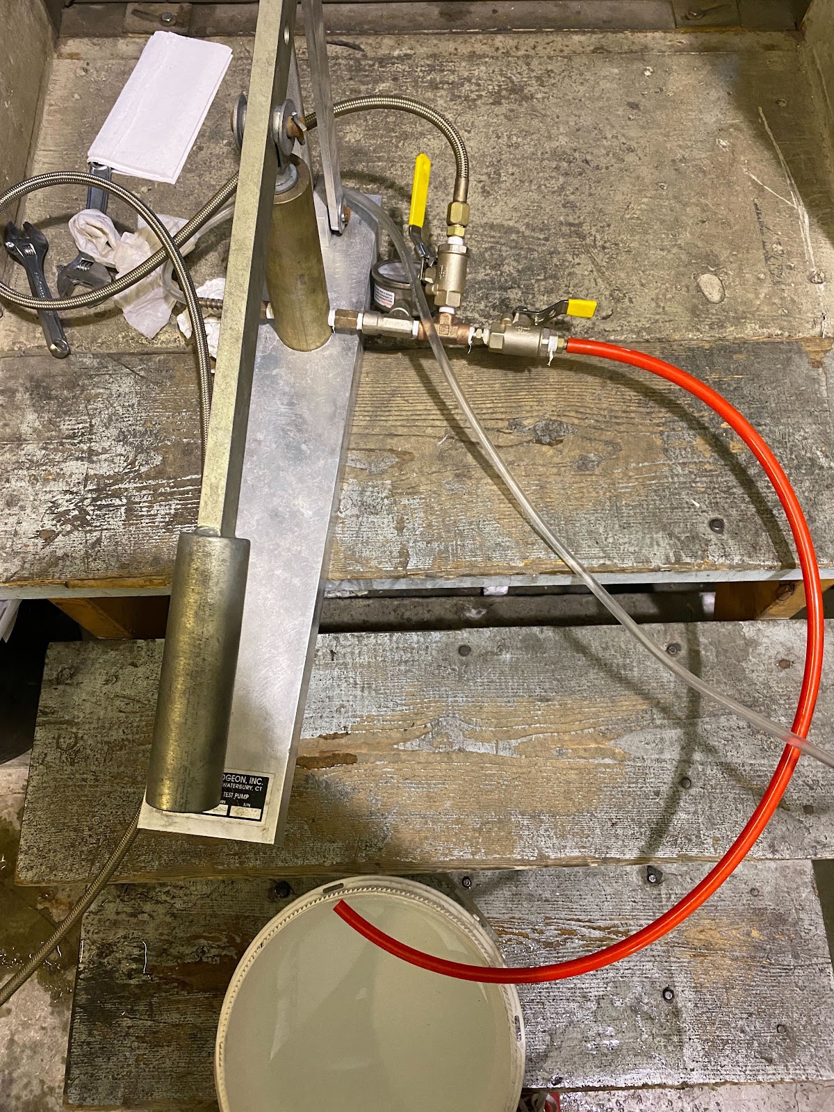
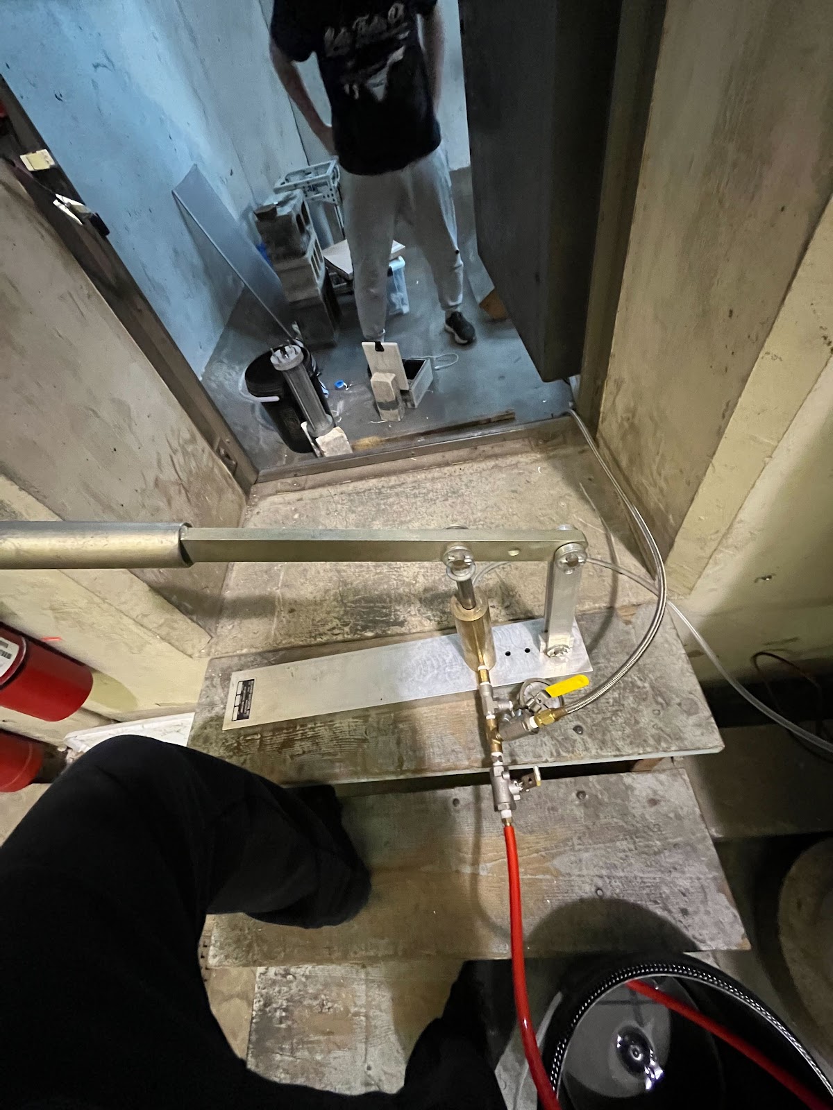
- Pump
- Fill 2 buckets with water, one for pumping and one for exit
connect reservoir hose to low pressure of pump, unclip hose
open red drain valve on high pressure side, close pressure valve
pump a few times until no bubbles appear in drain bucket
Pressurizing our motor
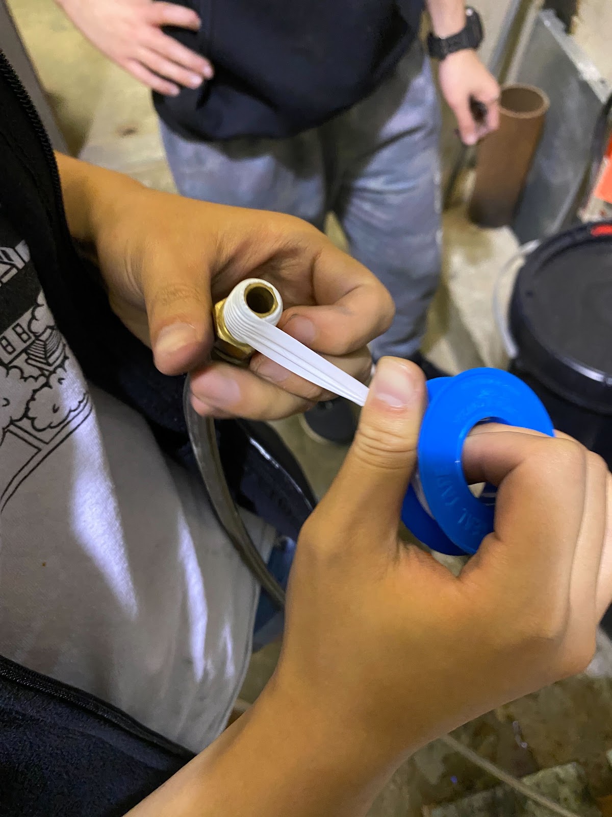
attach pressure hose to hydrostatic cap (use Teflon tape!)
open pressure valve on high pressure side till water comes out of the pressure transducer hole
attach pressure transducer
attach pressure transducer to DAQ
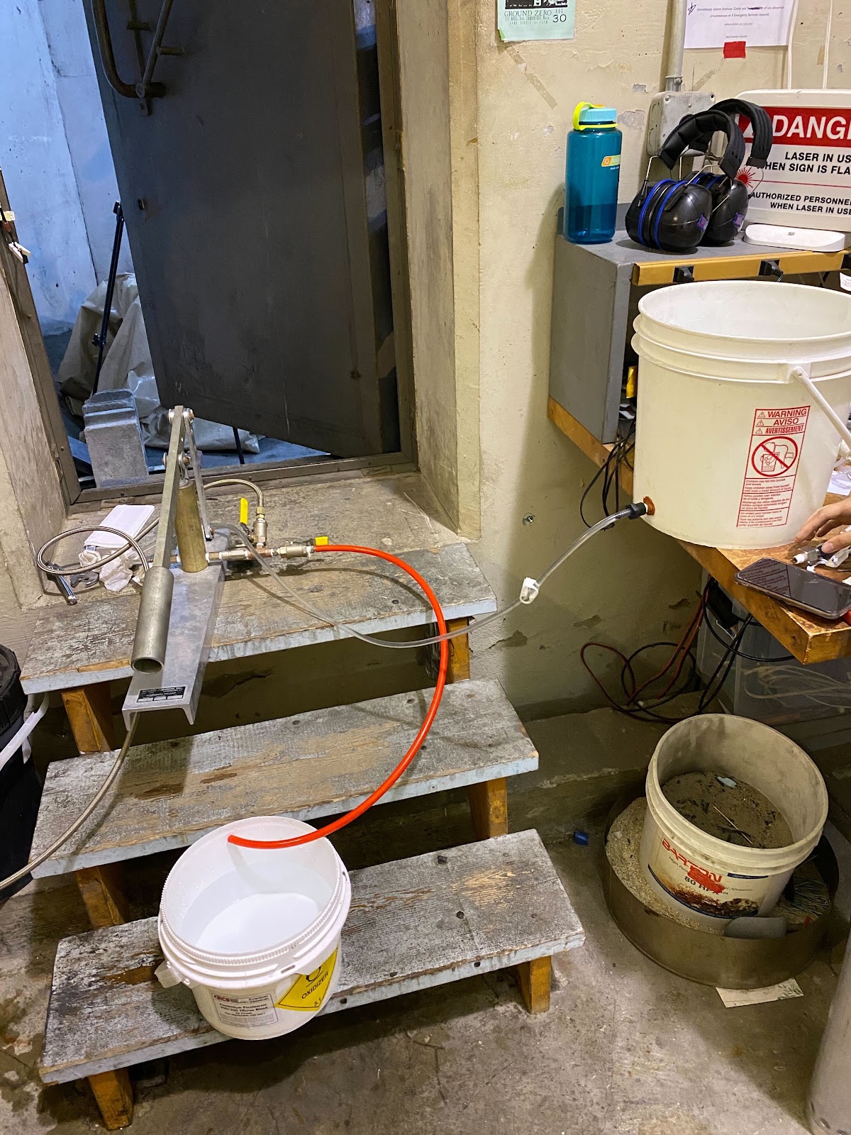
Hydrostatic Procedure:
Setup cameras, close blast chamber as much as poss.
Start up data collection
pressurize
start with a little bit then build up psi by 250 psi increments
call out pressure milestones, venting, etc.
check to make sure pressure is holding (if not, indicates a leak)
pause 1 min increments to check for leaks
Post Hydrostatic Test:
- open red vent valve to depressurize
- turn off DAQ
- drain water
- leave the place cleaner than you found it
More on testing procedure, emergency protocol, checklist can be found here


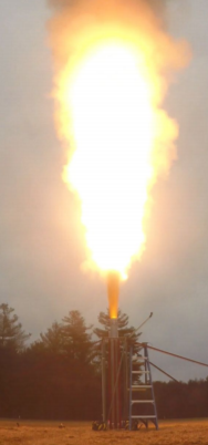
Static Fire
Why static fire?
Prove that the motor works as an isolated system
"Fail fast" and without blowing up other subteams' work
Gather data to validate your own simulations
Gain information that will help you iterate on your design in the future
Characterization of propellant (*C can be calculated with pressure and burn rate)
Safety materials, fire extinguishers, etc.
test stands, motor, ground stakes, ratchet straps, DAQ, igniters
Hardware like wrenches, screwdrivers, calipers, cameras, grease, shovel
charged computers, proper software
Snacks
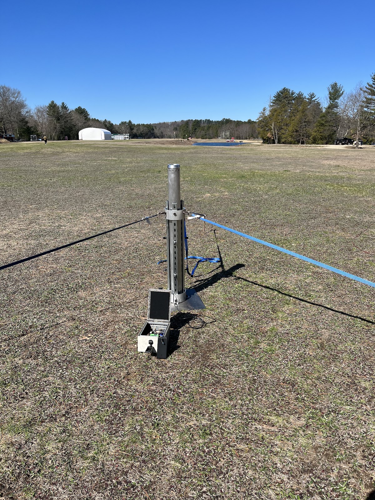
Firing Procedures Test Stand Assembly:
Teflon tape pressure transducer, set up load cell
Tighten/untighten bolts of test stand as needed
hit stakes into the ground
attach ratchet straps to test stand and stakes (don’t tighten)
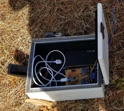
Attach wires to DAQ in protective box
Set up cameras
place motor in stand and attach transducers
tighten bolts as needed to secure motor
tighten ratchet straps
Data test (checking that DAQ works)
Procedure:
Now, we will talk about the static firing procedures. This is a list of actions that must be followed in the following order:
- Assemble the test stand, install the motor.
- Start the cameras and the data acquisition system.
- Send all but one person to a safe standoff distance.
- Connect the igniter to the ignition system and power it on to ensure it hasn't malfunctioned.
- Power off the ignition system and install the igniter into the motor.
- Power in the ignition system.
- Retreat.
- Make sure the range is clear and count down.
- FIRE!
- NEVER EVER approach a motor until all signs of combustion have stopped. Even if it didn't light, give it a full minute to make sure it wasn't a slow ignition.
Data Collection & Diagnosis:
We will now dive deeper into data collection. There are four main points that need to be taken care of:
- General observation of the firing - did the motor blow up, or does it seem to have been fired as intended?
- Videos of motor operation - these are vital in determining some of the hard-to-catch details, such as the slag coming out of the motor, or the igniter system that flies out. In general, you can tell a ton about the firing by going frame by frame on a good video.
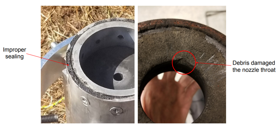
- Pictures of motor hardware pre- and post-firing. These help determine how the components held up during combustion and can be used to detect any anomalies or close calls to an explosion.
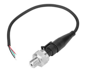
- Thrust and pressure curves as well as temperature data. This is very essential for overall rocket simulation, propellant characterization, and checking how accurate your simulations were. It is also very important for other subteam's work as they rely on the rocket simulation to design some of their components. You will want a thrust curve for your motor so you can figure out how high the rocket will go. A pressure trace is very critical to characterizing your formula, and for verifying if the motor had performed according to the simulation. And temperature data can be used to tune characteristic velocity as well as design insulation. Instruments named "transducers" are used to acquire such data, which can be seen below.
Load cell Pressure Transducer Thermocouple


Here are two post-firing pictures of a rocket motor to give an idea of how data collection, and more specifically pictures of the motor hardware, can help spot the flaws.
After shooting various quality videos and taking pre- and post-firing pictures of the equipment, it is important to know how to diagnose common failures. These consist of over-pressurization, thermal failure.
Over-pressurization occurs when the propellant produces too high of a chamber pressure, rupturing the motor case. Usually, this happens at the startup unless the design is progressive, or a large void is present.
Over-pressurization
Thermal failure occurs when the insulation protecting the case from combustion fails and the case melts down. Typically this is seen later in the burn when the temperatures have really been high for a long time. Sometimes this failure seems relatively gentle, and other times it looks just like an over-pressurization.

Thermal Failure
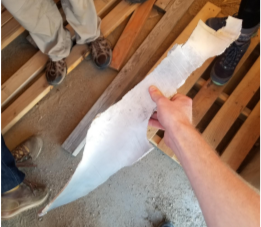
Sometimes we encounter issues that don't necessarily mean a failed design/propellant, such as slag and depressurization. However, fixing these issues allow our propellant to be more efficient.
Slag is when the propellant accumulates unburned aluminum around the nozzle exit, suggesting an inefficient burn. This may be due to too low a combustion temperature to adequately burn off all the aluminum fuel. Solving this issues may require tinkering with the propellant ingredients.
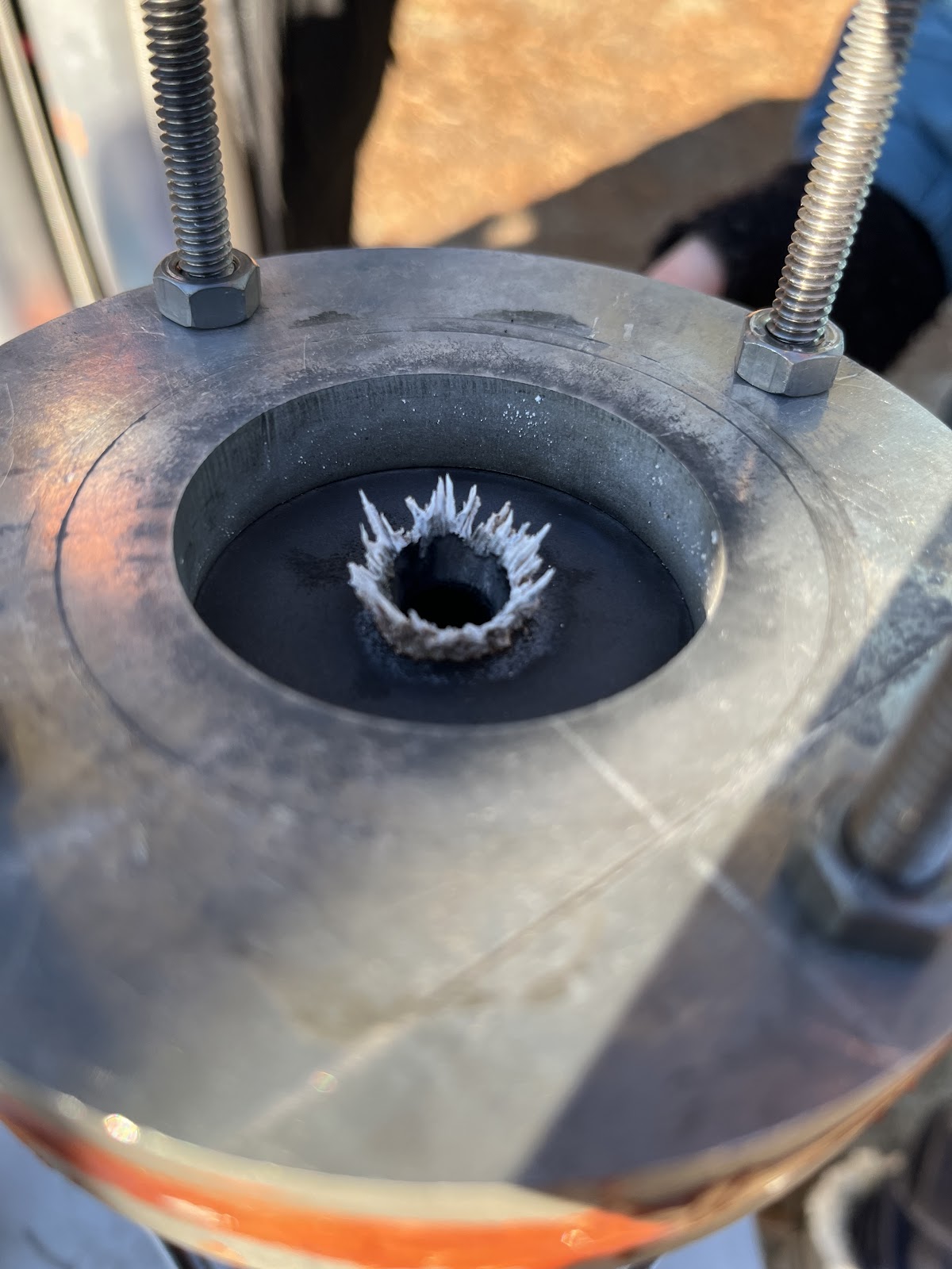
Slag
Depressurization is a loss of pressure in the motor due to a leak or hardware defect, which can significantly decrease the impulse of our motor. Such defects may not be easily noticeable, which is why it's important to analyze post-firing photos for any signs of breakage. This could be caused from many factors, from sliced O-rings, failed RTV adhesion, hardware defects, etc. but is usually identified by burned grease around sealed areas. Typically any anomalies in the hardware that could cause leaks will be found with a hydrostatic test.

Pressure Loss
Now, we will briefly talk about data acquisition. This system should be able to sample transducer as quickly as possible, at least 100 hz. Since transducers typically output a very small signal, it has to be amplified and a conversion function from voltage to force or pressure must be found. Also, the transducers should be pre-calibrated over the full range that they will see during the firing.
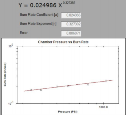
Our second to last topic is propellant characterization. As we know, burn rate and pressure are proportional, so by doing a series of burns with different throat sizes and fitting a curve to the data, it is possible to experimentally calculate the burn rate as a function of the pressure. This is also a good way to get c*. A minor but important point is that throat diameter before and after the burn should be measured if any slag accumulates.
Lastly, there are some general data processing tasks to do. Comparing maximum and average pressure to the simulated values (so that we can check if the characterization needs to be updated), comparing real thrust trace to the simulated values (so that we can check if they match, and think about if effects like erosive burning can explain discrepancies), calculate ISP and c* (so that we can check whether they are in line with what we expect from the propellant formula).
Photo and Video Tips
We have established the fact that good firing videos can help understand so much about the firing process. Hence, we shall now consider two main tips to shoot a good firing video and also look at some example firing pictures.
Firstly, a higher frame rate is often more important than a larger resolution, but both are good to have. And secondly, trying to get as many different angles as possible is very important.