Part | Component Status | Responsible Engineers |
|---|---|---|
| Booster Forward Retention Ring | Manufacturing Prep | Chad Meier 2023 |

Purpose
The forward retention ring serves 2 main purposes:
It retains the forward closure from sliding past the end of the motor casing.
It couples the motor casing to the mission package tube.
Requirements
Must withstand the force applied by the forward closure (8836 lb)
Must be able to interface with motor casing (3.75”)
Must be able to interface with mission package tube (3.9”)
Design
In order to accomplish the requirements, certain design considerations were made. The forward closure presses upward on the aft end of the FRR. The force it applies is equal to the chamber pressure times the inner cross-sectional area of the motor casing. The FRR must be able to withstand the load of the peak pressure (given by the Propulsion Sub-team) with a safety factor of 2. Working with Propulsion, we decided that the FRR will have 2 rows of 12 ¼-20 holes that interface with the motor casing. This was based on calculations that Prop did for the motor casing.
The calculated force acting on the FRR was calculated using the following data:
(force) = (peak camber pressure) * (inner cross-sectional area)
8836 lb = 800 psi * pi*(1.875 in)^2
The bolt torque for the aft bolts was set to 3 ft-lb of preload. This is about hand tight with a wrench. The tension in each bolt resulting from this torque is about 960 lb. This was calculated using the method in this article: https://www.portlandbolt.com/technical/faqs/tension-vs-torque-explained-sort-of/
(bolt tension) = 12*(preload torque)/((torque coefficient)*(bolt major diameter))
torque coefficient used: 0.2
960 lb = 12 * 3 ft-lb /(0.2*0.25)
The FRR was designed to be made from 6061 T6 aluminum. This makes the part affordable and easy to machine. Later designs may be able to be made from 7075 alloy aluminum, which has a higher yield strength and a higher cost. Using 7075 could allow for a more lightweight design, saving weight on one of the heavier parts of the rocket.
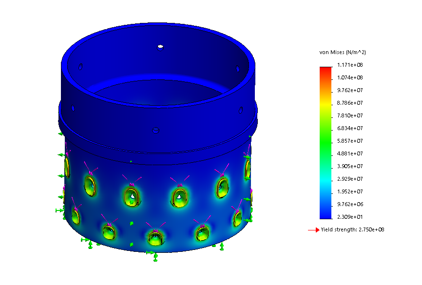
Using FEA, I decided that this cross-section worked under the following conditions:
8,836 lb from the forward closure
3 ft-lb preload on the bolts (this puts 960 lb tension in the bolt)
FRR made of 6061 T6 Aluminum

This design has straight walls, unlike the sustainer FRR. This is because having 2 rows of bolts would make this quite difficult to manufacture. Instead, the wall thickness was decreased until the safety factor was a little above 2. The safety factor is 2.35
For the forward part of the FRR, which is designed to interface with the mission package tube, the design was much simpler. This is because the weight of the airframe rests on the FRR shoulder. The main job of the forward-most screws are to restrict rotation about the central axis of the rocket and bending about the other axes. The surface that the screws attach to is extra long to prevent this kind of bending.
These screws also hold the mission package tube on during the descent back to the ground, but there are no major forces associated with this. 4 10-32 screws were used for this.
Manufacturing
TBD - waiting to return to campus
The plan is to use one of the semi-CNC lathes in The Deep as well as a radial indexer.
Testing
Static Fire?