Unless stated otherwise, connector positions are described as looking at the outside of the box.
Motor Driver Box:
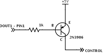
LED Control:
DOUT1 - pin1 on motor driver DB15 connector
+5V taken from LED driver
External connector shared with e-stop:
Bottom right - LED +
Bottom left - LED -
Motor Driver:
Roboteq I/O connector:
1 - DOUT1 - see led control above
2 - TX - green - top left on cpu connector
3 - rx - blue - top right on cpu connector
4 - DIN1 - e-stop - top right on e-stop connector
13 - gnd - power switch led gnd
14 - 5v - power switch led + and e-stop top left
CPU Box Connector:
top left - green - roboteq tx - roboteq I/O pin 2
top right - blue - roboteq rx - roboteq I/O pin 3
bottom left - power ground
bottom right - power vbatt
Power Switch Wiring:
C1 - power control
NO - vbatt
NC - ground
LED+ - roboteq i/o pin 14 (5v)
LED- - roboteq i/o pin 13 (gnd)