Unless stated otherwise, connector positions are described as looking at the outside of the box.
Motor Driver Box:
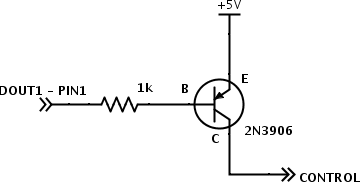
LED Control:
DOUT1 - pin1 on motor driver DB15 connector
+5V taken from LED driver
External connector shared with e-stop:
Bottom right - LED +
Bottom left - LED -
Motor Driver:
Roboteq I/O connector:
1 - DOUT1 - see led control above
2 - TX - green - top left on cpu connector
3 - rx - blue - top right on cpu connector
4 - DIN1 - e-stop - top right on e-stop connector
13 - gnd - power switch led gnd
14 - 5v - power switch led + and e-stop top left
CPU Box Connector:
top left - green - roboteq tx - roboteq I/O pin 2
top right - blue - roboteq rx - roboteq I/O pin 3
bottom left - power ground
bottom right - power vbatt
Power Switch Wiring:
C1 - power control
NO - vbatt
NC - ground
LED+ - roboteq i/o pin 14 (5v)
LED- - roboteq i/o pin 13 (gnd)
CPU Box:
Arduino Shield <-> Power Board
Nostromo's Wiring:
| line | Power Board Label | Arduino Label | Arduino Pin |
|---|---|---|---|
| Radio power control | Vsense | VBAT | A4 |
Servo power control | Raux | RAUX | A3 |
Vbat control | Rmain | R5 | A2 |
12v control | R12v | R12 | A1 |
Servo pwm | Servo | SRVO | A0 |
gnd | Gnd | GND | GND |
+5 | 5v | 5v | 5v |
NC | 9v | Vin | Vin |
Other Kayaks:
| line | Power Board Label | Arduino Label | Arduino Pin |
|---|---|---|---|
Radio power control | Sense | unwired | A4 |
Servo power control | 6v | RAUX | A3 |
Vbat control | Not labeled | unwired | A2 |
12v control | 12v | R12 | A1 |
Servo pwm | Servo | SRVO | A0 |
gnd | Gnd | GND | GND |
+5 | vin | 5v | 5v |
power reset | Not labeled | VBAT | 12 |
Modifications and Bodges:
Power Board:
- Vbat control (unlabeled between 12v and 6v) must be wired to pin 1 of its optorelay (immediately below the left main power connector)
- Radio power control must be manually wired to a 2-pin KK connector (along with 5V) in the proto area
- Optorelay for 6v control must be double up, and its associated resistor (vertical and to the left) halved to ~300 ohms
Arduino Shield:
- Radio power control and VBat control must be manually wired (see tables above)
- 12v control line transistor can be bypassed
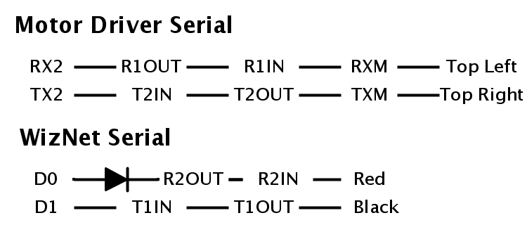
- motor driver is wired to serial uart 2
- gumstix is wired to serial uart 1
- tmp102 temp sensor resides on i2c bus
- sbus wired to uart3
- wiznet wired to default uart (shared with usb)
Arduino Serial Details: