Return to Learning Curriculum
LS2: Basic engine design - compressible flow in rocket nozzles
Lecture Zoom Recording Pt.1 Lecture Zoom Recording Pt.2
Original Author: Laurens Voet, lvoet@mit.edu
- Great links
Anderson - Fundamentals of Aerodynamics (Part 3 on Inviscid, compressible flow):
A great youtube video explaining nozzles and their flow: https://www.youtube.com/watch?v=p8e8A3sdVOg
Theory
Fuel and oxidizer flow at specific rates through the feed system (see Topic 4) and are combined in the combustion chamber of the rocket. The combustion process results in products (i.e. the products of combustion after combining fuel and oxidizer) flowing out of the combustion chamber into the rocket nozzle as a gas. The combustion chamber, therefore, determines the flow conditions at the entrance of the rocket nozzle. In this LSET, we consider the flow of the combustion products through the rocket nozzle.
Mass Flow
Let’s simplify the problem first by looking at a practical example. Consider the flow through a water hose. In this case, the mass flow rate (LSET 1) through the hose is determined by the spicket (hose entrance) and is constant. If we change the cross-sectional area at the exit of the hose, the velocity of the water at the exit will change correspondingly. This is illustrated in Figure 1 below.
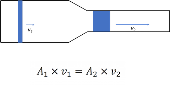
Figure 1: Incompressible channel flow: a reduction in area results in an increase in velocity.
We can use the general definition of mass flow to explain this behavior:
In this equation, is the density of the fluid, u is the velocity and A is the through-flow area. From the equation we can see that, if the mass flow and the density of the fluid are constant, decreasing the exit area will increase the exit velocity.
The principle of conservation of mass through a channel is intuitive. Since mass through a nozzle can neither be created nor destroyed, all mass flow entering a device (e.g. a nozzle, a tube, a channel, really anything) needs to exit the device as well.
Compressibility
For water (i.e. a liquid) the assumption of incompressibility works very well, meaning if we apply pressure on an element of water, the volume of this element will (approximately) not change. For gases, the assumption of incompressibility (i.e. the volume of an element of air does not change when applying a pressure) works well in most cases of our daily lives (e.g. when walking around, when driving our car). When driving, the air molecules hit your car, but are then quickly displaced around it.
However, in a lot of aerospace applications, the range of speeds encountered is a lot higher. At such speeds, assuming incompressible flow is not correct anymore. Instead of being quickly displaced, as in the car example, the individual molecules will come closer together before getting displaced.
Including this compressibility effect, the behavior of any flow at high speeds through a channel will change. This means that, when changing the area of the channel, the velocity will not just linearly vary as well (as described by the previous equation). The changes in density have to be taken into account as well. This is the field of compressible flows, which is very important in rocket nozzles.
In the previous discussion, we discussed “low” and “high” speed flow behavior. We need a metric to define what these “low” and “high” speeds mean and consequently, where incompressible and compressible flow holds. The speed of sound is used as such a metric to distinguish between these two behaviors.
The Speed of Sound
The speed of sound is the velocity at which the sound travels through a medium. This means that its value must depend on the specific medium considered. For ideal gases, the speed of sound can directly be related to the static temperature of the gas. We model the combustion products as an ideal gas (see the section on ideal gas). We can calculate the speed of sound as follows:
Here, (the ratio of specific heats) and R (the gas constant) and T (temperature) are specific to the medium. For air
and
. For the combustion gases (i.e. the result of fuel and oxidizer) encountered in the rocket nozzle, these properties are usually tabulated for different fuels and oxidizers at different mixing ratios. We will cover these gas properties in more detail in the next LSET.
There is more behind “speed of sound” than just the velocity of sound waves. The speed of sound is used to describe how fast “information” travels through the medium. In the case of sound, this information is a pressure perturbation originating from the source of the sound. For example, when speaking, your throat makes a pressure perturbation, which travels all the way through your mouth and then through the atmosphere until it reaches someone’s ear, who can hear it. In our channel flow example, we can also consider a change in our channel area as a perturbation. Thinking about the speed of sound as the speed at which information can travel helps to explain the different fluid behavior for subsonic (i.e. relatively slow) flow and supersonic (i.e. relative fast) flow.
Let’s consider a simple example, illustrated in the figure below. The dots on the horizontal axis in the figure represent the sound source traveling to the right at different instances in time; the circles represent sound waves emerging from the source as they travel away from it. In subsonic flow (left figure), the information (i.e. the sound waves) travels faster than the flow itself: V < Vsound. This means that perturbations are able to travel upstream in the flow. We see that because, at any instance in time, sound waves are present in front of the source. However, in supersonic flow (right figure) the information travels slower than the flow itself: V > Vsound. This means that the perturbations cannot travel upstream. We can see that from the figure since the sound waves are always behind the source. The faster the source moves, the smaller the angle of the cone .

Figure 2: Sound waves propagating from a source in subsonic (left), sonic (middle), and supersonic flow (right).
Mach Number
The velocity of the flow, relative to the speed of sound, is called the Mach number: The equation for Mach number is: , where u is velocity and a is the speed of sound.
This means that a subsonic flow, will have and supersonic flow will have
. Sonic flow means
. The sonic flow serves as a boundary between two very distinct fluid behaviors. Subsonic flow is often intuitive, as this is the type of flow that we encounter in our daily lives. Supersonic flow has very different and usually non-intuitive behavior.
In compressible flows, we usually don’t use velocity but Mach number. By using velocity, we don’t know in which regime (i.e. subsonic or supersonic) we are operating, because this all depends on what the speed of sound is. By using Mach number, we know exactly if we are subsonic or supersonic and therefore, we have a good idea of what the flow behavior is like.
Choked Flow
As already said, the flow behavior changes drastically going from subsonic to supersonic flow. The main example that you should remember is what happens with Mach number when the flow area changes. This is illustrated in the figure below.
In a subsonic flow, as we just discussed with the hose problem, if we decrease the flow area, the velocity (and therefore also the Mach number) increases.
In supersonic flow however, if we decrease area, the flow slows down and the Mach number decreases. This sounds very non-intuitive.
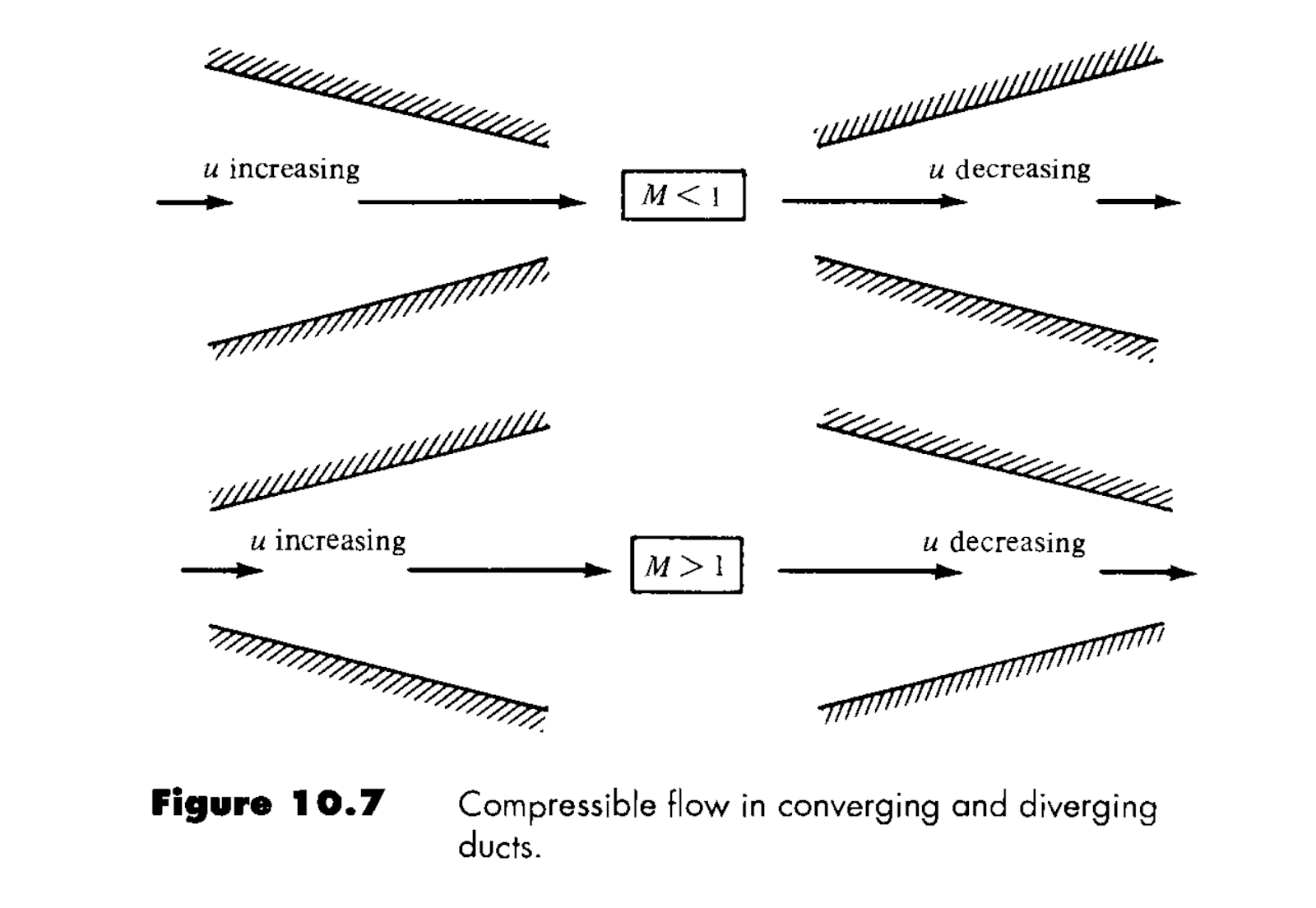
Suppose we have M<1 at the inlet of a channel and we continue to shrink the area until the flow speeds up to M=1. To increase the Mach number even further, we now have to increase the area, since the flow behavior switched from subsonic to supersonic. That means that, at the point at which the flow area is smallest in the channel, we will have M = 1. This is a very important result. In the throat of the rocket nozzle, we therefore always have M = 1, given that the exit flow is supersonic. If the exit flow is subsonic, the Mach number at the throat will be M < 1. When Mach number at the throat is sonic (i.e. M = 1), the flow through the nozzle is called “choked”. This paragraph basically summarizes why the rocket nozzle looks the way it looks. To have the exhaust velocity as high as possible, we first decrease the area of the nozzle up to M=1, and subsequently increase the area until M = > 1.
Ideal Gas Law
Let’s now look at how thermodynamic quantities like pressure, temperature and density are related in a general flow. The ideal gas law gives the relation for ideal gases (such as air):
(1)
(2)
Note that in equation (1), the R is the universal gas constant, whereas in equation (2) R is the gas constant for air. This equation says that, for example, if we heat up (i.e. increase the temperature T) a gas at constant pressure p, the density will decrease to keep the pressure constant. The quantities like pressure, temperature and density in the ideal gas law are called static quantities. These are the quantities you would go measure when you would go STAND outside with a thermometer or barometer.
Total Conditions
In the previous discussion, the word “stand” is highlighted. The question that we can ask is: would our pressure reading change if we stood outside compared to if we would drive our car on the highway and stick the barometer out of the window?
The answer is: YES! This goes back to our discussion of slow and fast flows. The faster we would drive on the highway, the more our pressure reading would change compared to our reading at standstill. More intuitively, if we stick our hand out the window and accelerate the car, we will feel the pressure increasing on our hand the faster we are driving. This can be seen by looking at the Bernoulli equation:
On the left-hand side, we have the total pressure, which is composed of the static pressure component and the dynamic pressure (velocity component). The dynamic quantity can be rewritten in terms of Mach number for compressible flows. The total conditions are usually indicated with a subscript ‘t’ or ‘0’.
In conclusion, we have to distinguish between two types of thermodynamic quantities, namely static and total quantities. Where the static quantity (e.g. pressure) does not include the Mach effect, the total quantity measures the pressure as if we would slow the flow down to M=0 (imagine decelerating the flow on our hand out the window).
Conservation Equations
There are 3 conservation equations that hold in any physical process:
Conservation of mass: mass will never be created or destroyed. However, mass can be transported (i.e. flow).
Conservation of energy: energy will never be created or destroyed. However, energy can be transformed from one form to another.
Conservation of momentum
** In your fluids and thermodynamics classes, you will learn more about these equations, and how they are derived. For now, we will accept these conditions and apply them to our relevant concepts.
These conservation equations can be related to the total quantities that we just talked about. Without derivation I will state:
Total temperature is constant in any process where you don’t add heat. This relates to the conservation of energy. This means that throughout the rocket nozzle (after the combustion chamber) the total temperature will remain constant.
Total pressure is constant in any lossless process (i.e. when we don’t take friction into account). This is usually a good assumption for high-speed flows. This means that throughout the rocket nozzle (after the combustion chamber) the total pressure will remain constant.
Isentropic Relations
Note there are some intimidating equations ahead, but don’t fret! Knowing the derivations of these is not important for us right now. What’s really important is to understand how these quantities change as you increase/decrease different variables in the equation.
The relations between the static and total quantities for temperature and pressure are given below. They are called the isentropic relations. We won’t derive these equations here, but you can find the derivation of these equations in any compressible flow textbook (J. Anderson: Fundamentals of Aerodynamics).
In these equations, 
The Mass Flow Equation in Compressible Flows
The first equation in this LSET (i.e. the mass flow equation) is not very useful in compressible flows, since it involves velocity. A better way to express the mass flow equation is to use total quantities and Mach numbers. Rewriting the first equation using the ideal gas law, and the isentropic relations for temperature and pressure, results in:
In this equation, A is the cross-sectional area at some point along the nozzle. This equation seems a lot more complicated. If we rearrange it, we will get more insight into the flow through a nozzle:
On the left-hand side, we see the mass flow rate of the gas and total quantities. All these quantities are set by the combustion chamber and are assumed to be constant. On the right-hand side, we see the area and the Mach number. This equation will thus allow us to calculate the Mach number at each location in the nozzle, given an area. From a design perspective, it allows us to shape the nozzle area if we want a specific Mach number distribution throughout the nozzle.
Thermodynamic Quantities Throughout a Rocket Nozzle
We already discussed that the thermodynamic quantities that are obtained when the flow is brought to a standstill are called ‘total’ or ‘stagnation’ quantities/conditions/states. From the conservation equations, we saw that these conditions, namely total temperature and total pressure are constant in the rocket nozzle. However, we did not talk about what happens with the static quantities throughout the nozzle.
We know that the measured pressure and temperature in our combustion chamber are approximately the total quantities since the Mach number in our combustion chamber is very low. We can see that from the following equation relating the static temperature with the total temperature::
Since M is very low (~0) in the combustion chamber itself, the second term in the brackets is approximately zero, and we have T_t = T*(1)
As the Mach number increases in our nozzle, the static quantities will change. We can use the isentropic equations, as described above, to calculate how much the static pressure and temperature change throughout the nozzle, based on the Mach number at that location. This is illustrated in the figure below.
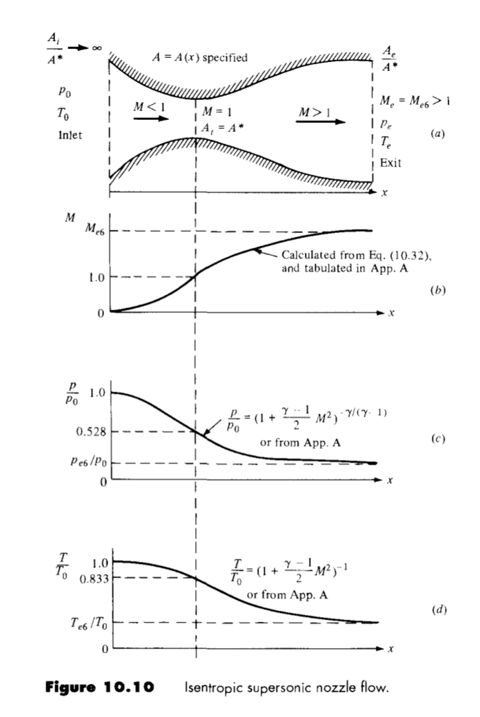
There is one special point in our nozzle, and that is the throat. From our previous discussion, we know that this is the point where, if the conditions are right, the flow will switch from being subsonic to supersonic. At this point, where the cross-sectional area is the smallest, M=1, or the flow velocity is exactly the speed of sound.
Coefficient of Thrust
After having designed the rocket nozzle shape, we must have a measure of defining its performance. In other words, how good is our rocket nozzle at expanding the combustion products, starting at the combustion chamber until the ambient? The thrust coefficient Cf is used as such measure:
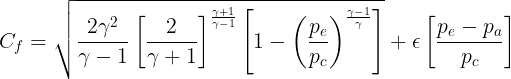
You can use this coefficient (don’t worry about the derivation of this equation) to define the nozzle aerodynamic performance. As we will see in the next LSET, there is another quantity, namely the characteristic velocity c*, characterizing the performance of the combustion chamber itself. Both quantities can be combined into a more widely used performance parameter of rocket nozzles, namely the specific impulse:
More on this in the next topic.
Return to Learning Curriculum