Materials
- Hard goods box (6-32 bolts, 4 1/4-28 bolts, 4 1/4-28 bolts with washers, 3 chamfered 6-32 bolts, eyenut, cotter pin, 10-32 nuts, quicklinks)
- Integrated piston
- AV tower
- Recovery guard
- Payload stack
- Payload bulkhead
- NC coupler
- Antirotation rod
- Skinny god nut
- Integration stands
- Firebolts with tender descender extensions
- Tender descenders and loops
- Teflon tape
- Connecting loops (3)
- Black Powder
- Gloves
- Popsicle sticks and weigh boats
- Goggles
- Paper funnel
- Scale
- Hex key set
- Needle nose pliers
- Adjustable wrench
- Pliers
- Clocking tool
- Phillips Head Screwdriver
- Blue tape
- Gaff tape
- Electrical tape
- Wire Strippers
- Printed or original copies of the Hermes II Lines Diagram and Tender Descender Integration Notes
Procedures
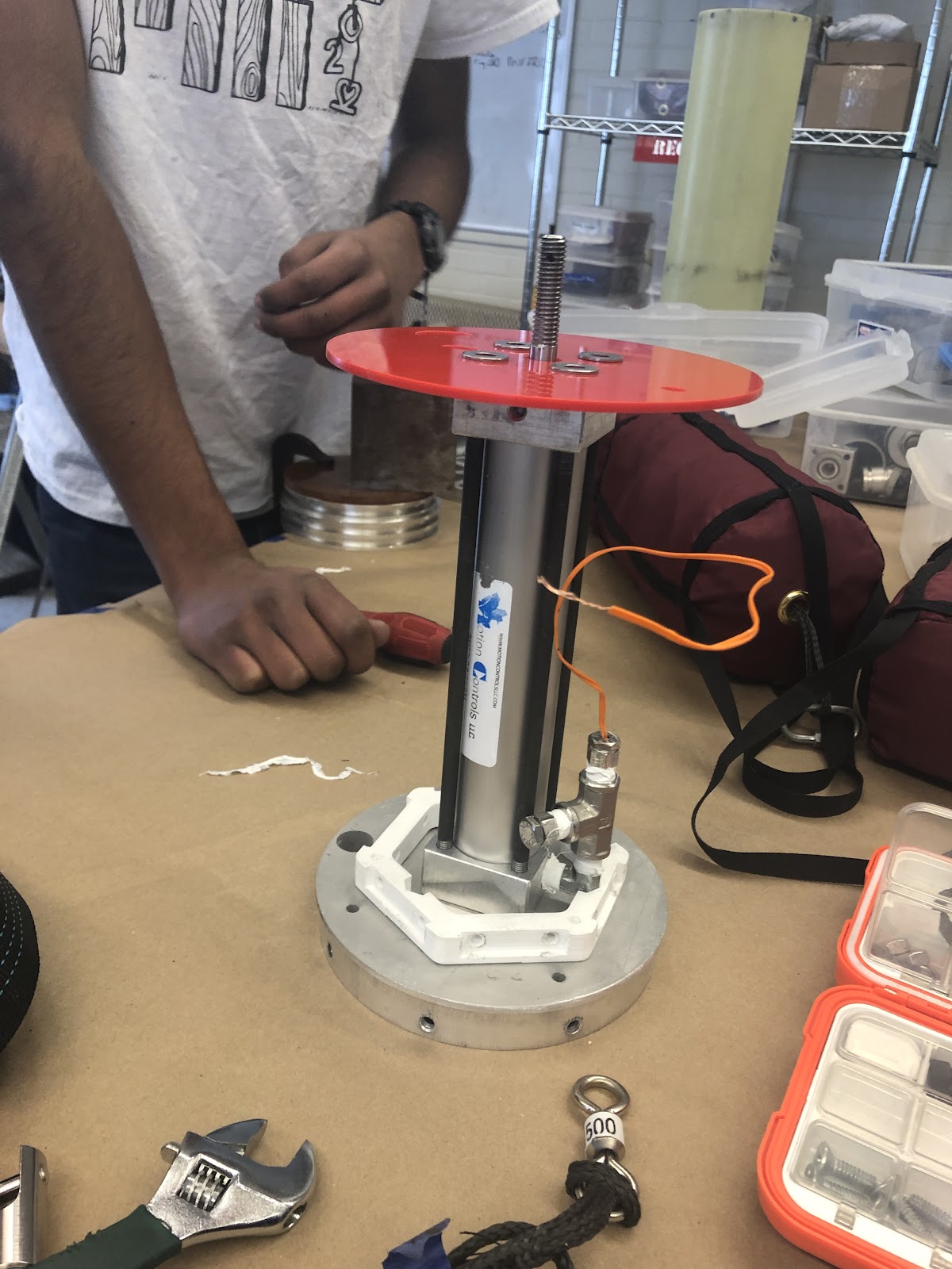
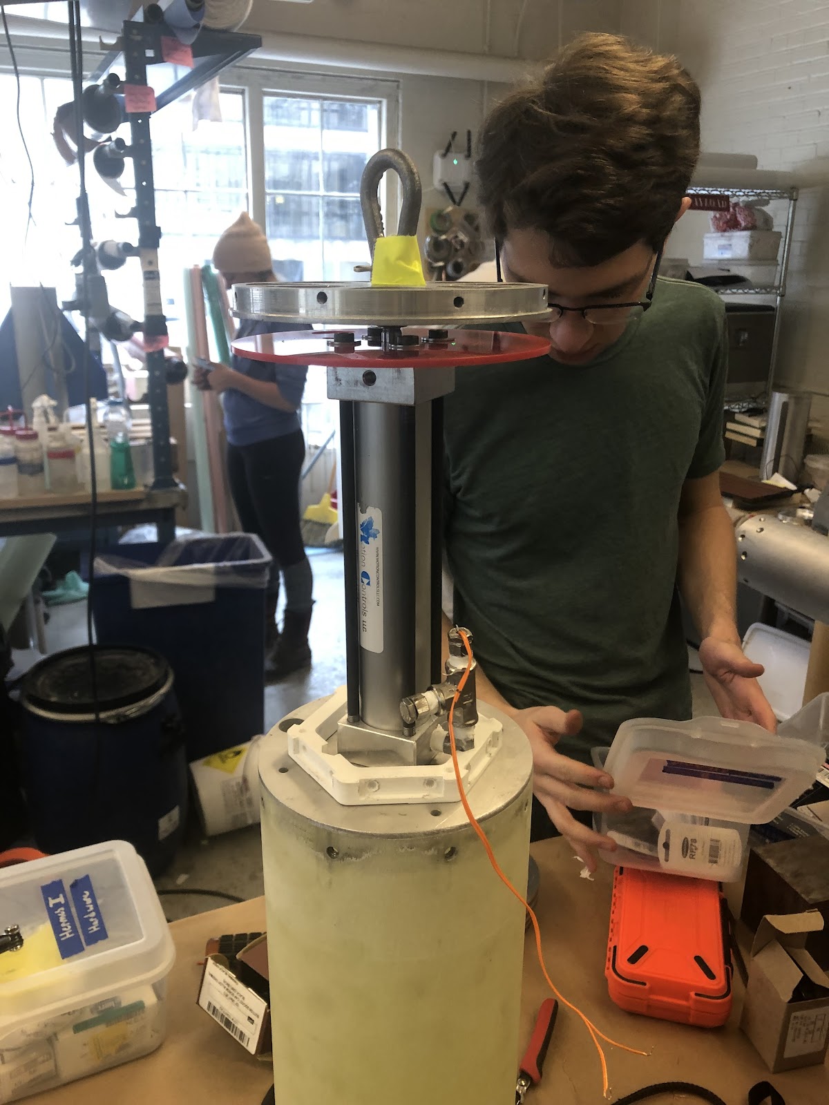
Attach integrated piston to payload bulkhead with ¼-28 bolts, ensuring the bolts are very tight! The clocking matters, clocking mark to be added
Attach the integrated AV tower to payload bulkhead with 6-32 bolts. The elbow/ tee fitting assembly must be turned slightly inward in order to fit the AV Tower on top.
Wire piston to AV tower- make sure to strip the end of firebolt and trim down appropriately.
Attach recovery guard to piston using ¼-28 bolts and washers
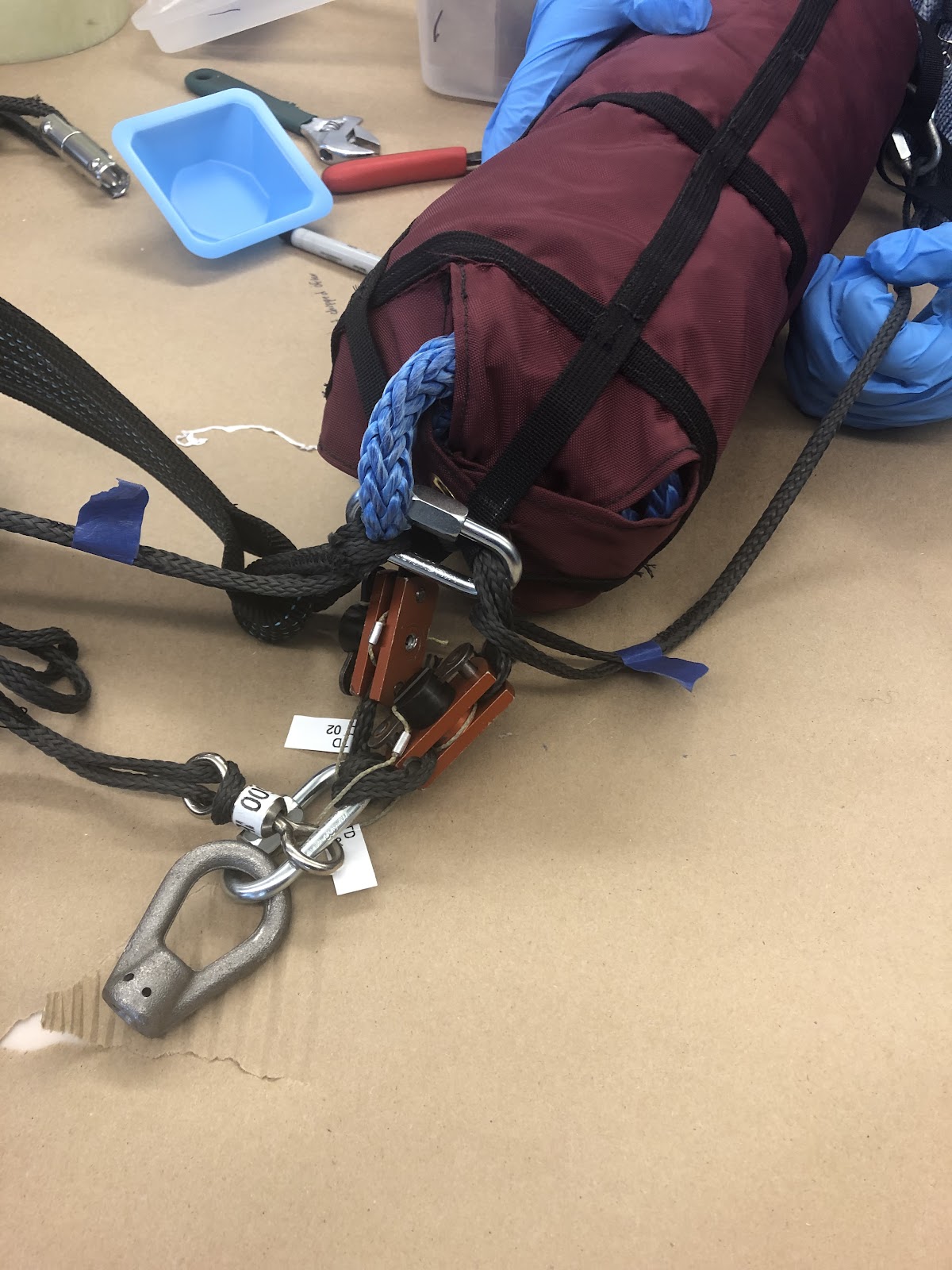
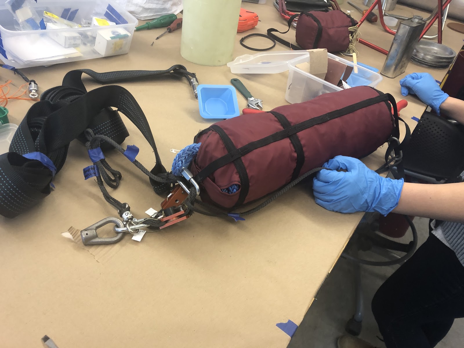
Integrate soft goods and tender descenders- refer to Hermes II Lines Diagram and Tender Descender Integration Notes
Another QL at end of MP Riser to Motor Section Riser (wide Black) and Main Riser (Blue Spectra)
Main Bag Bridles and load-bearing riser to QL to black Drogue Swivel to drogue riser
Drogue riser to QL to drogue lines
Connect bottom of drogue bag to Motor Riser inside swivel
Connect Motor Riser to loop to swivel to loop to eyebolt
For tender descenders from Main Bag TD loops to eyebolt:
After lines are integrated according to the Lines Diagram, attach the tender descender halves loosely sandwiched together. Integrate one first.
- Fold a funnel out of paper and tape it to the black powder input hole
Put on goggles and safety goggles
- Teflon tape e-matches with TD extensions 4-5 times around tightly
Measure out and pour in 0.2 g black powder through the funnel
- Hand screw in the e-match to BP-input hole
- Tighten e-match with wrench
Hold TD loops with the appropriate items attached (see below item ix). Push towards center to ensure the loops don't get caught. Check that the loops slide freely. Repeat integration with second TD (steps ii-ix)
The TD loops have 2 distinct sides:
- longer side has 5 things:
- main loop 1
- locking loop
- main loop 2
- load bearing riser
- the QL to main riser
- shorter side has 1 thing
- QL to eyebolt *attach the TD retention loops to the QL
- Take a checkout photo of each color set of loops (blue, purple, pink)


- longer side has 5 things:
- Connect white 1500lb swivel, TD loops, and TD restraining loops (thin yellow) to QL. Attach QL to eyebolt.
TIGHTEN ALL QUICKLINKS WITH A WRENCH
Add torque stripe to each quicklink after tightening
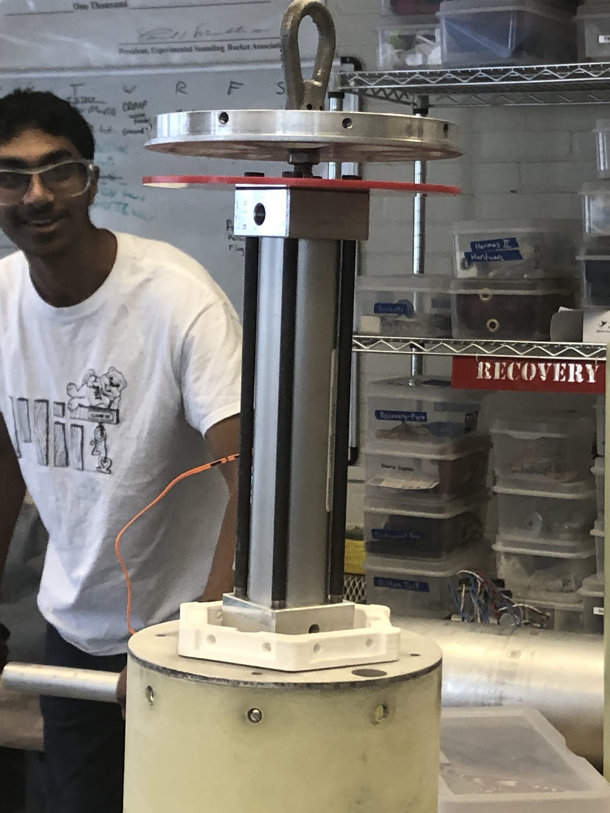
Screw antirotation rod into diaphragm with locknut. Screw on skinny god nut all the way down and add a washer. Place diaphragm on.

Next, hold the god nut with small pliers and screw the eye nut tight. Insert cotter pin. Fold down legs and stick gaff tape over the spikey bits of the cotterpin!
Pull up on diaphragm and use wrench to tighten nut upwards until fully tightened.
Take checkout photo of diaphragm & recovery guard assembly
Wire tender descenders
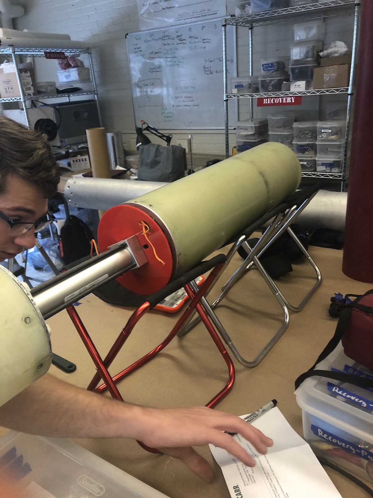
Set up integration stands. Stand piston-diaphragm assembly and cup close to each other.Thread main bag with lines and tender descenders through cup, so tender descenders are close to the diaphragm. Pull tender descender wires through half-moon shaped hole and attach tender descenders to eye nut.
Attach Payload Stack (see Payload Stack instructions)
Wire Payload Stack to AV tower
See Payload Stack integration checklist for checkout photos
Check continuity.
Push cup (with main bag, TDs and lines) onto diaphragm and secure with 10-32 grub screws. To line up, use higher holes on diaphragm and clocking mark on cup.
Take video of and conduct shake test with all of the soft goods attached inside the cup- Nothing should come lose!
MAKE SURE DROGUE RISER IS NOT TANGLED WITH THE MOTOR RISER
Slide mission package tube over all components- make sure to line up the 4 screw holes
Take checkout photo of MP tube alignment with screw switches
Push in shear pins and cover with tabs of gaff tape
- Take checkout photo of shear pins
Screw in nosecone coupler to the MP tube and payload bulkhead with 10-32 flatheads with a 100 degree chamfer. Don't screw in bolts all the way until all 3 of them are in.
Attach nosecone and nosecone tip