THIS PROCEDURE IS OUT OF DATE AND FOR REFERENCE ONLY. FOR CURRENT PROCEDURE SEE Hermes III Fin Leading Edge (FC005) Manufacturing Procedure Version II
Purpose
The leading edge (LE) protects the fin from the aerodynamic heating. It also moves the elastic center and the center of mass forward. It adds considerable stiffness to the fin. It takes two people around 12 hours to make a set of leading edges.
Materials
For Machining:
Raw Materials:
- 1/4" Thick 316 Stainless Steel Plate
- Fin Preform (FC002). For testing fit.
Tooling and Machines:
- 2x 1/8" TiAlN Coated Carbide 4 Flute End Mill for Stainless Steel (McMaster 8883a11)
- 2x 1/2" 15 Degree Tapered HSS OR 1/4 to 1/2" Carbide 4 Flute End Mill
- Mill (At least 5000 rpm and set up for mist or flood coolant)
Fabrication
Machining
Machining stainless steel is difficult. Do not expect the process to go as smoothly as machining aluminum. If you have never worked with stainless steel before, ask for help, expect to break an endmill or two, and buy extra stock and tooling.
For the slots, using a slot saw works fine with phenolic and aluminium. But for stainless steel, HSS tools performs very poorly and it's better to do the slots with an end-mill.
I. Making the Blanks
- Get sheet stock that has the thickness of the final leading edge.
- If you have not used the waterjet before, ask for help.
- From the CAD model, make a .dxf drawing of the part. Check dimensions.
- Using the related Waterjet software, copy-paste and orient the part such that you can get as many parts from the stock as possible. Make sure that all of the pieces fit in the frame of the stock.
- Check settings related to thickness, material etc., make sure they are correct.
- Follow the procedure for waterjetting. After getting the first piece, make sure dimensions are correct.
II. Machining the Slot
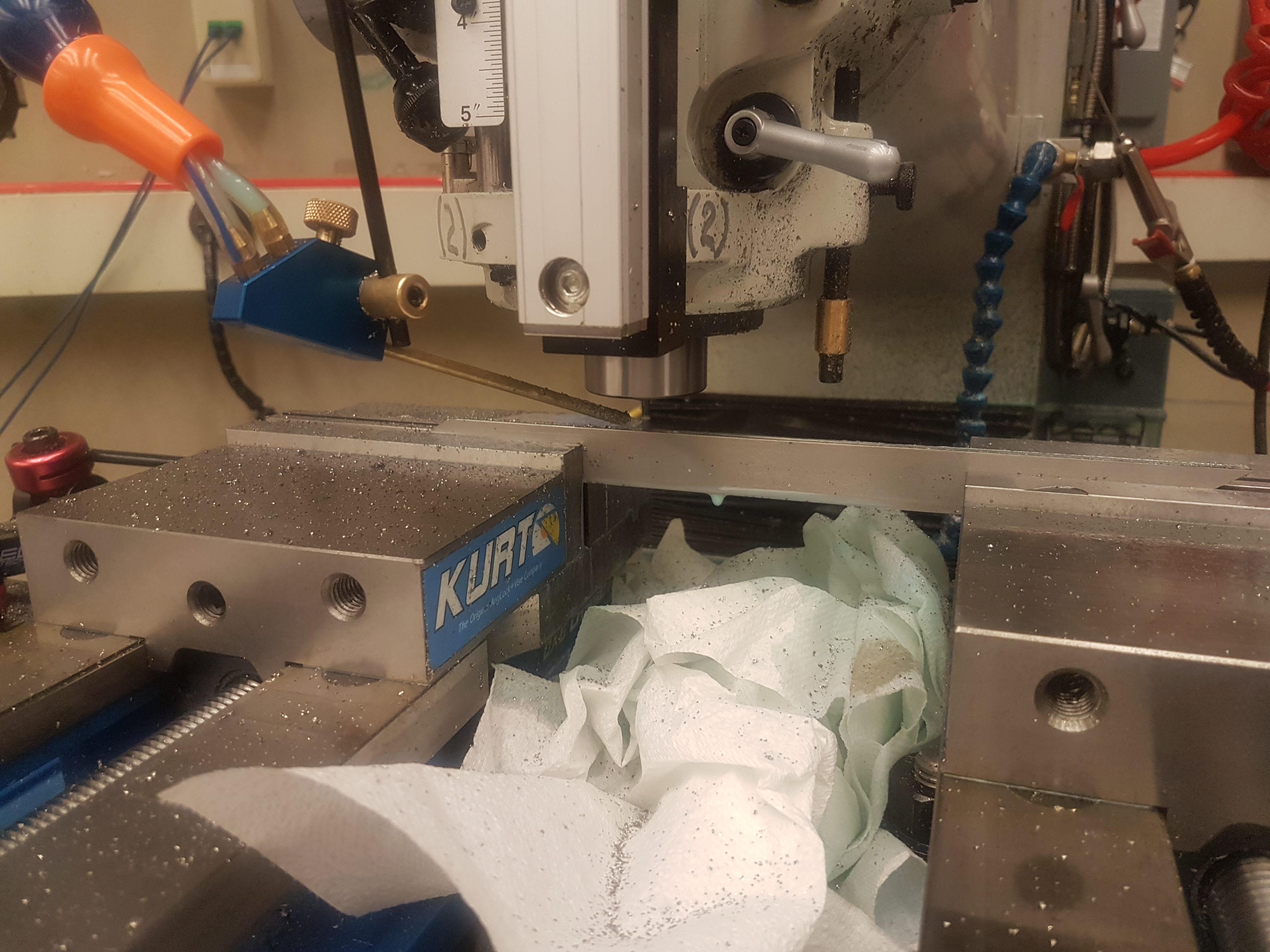
Figure 1: The leading edge set up between two vises. Note the position of the coolant nozzle and the paper towels to contain the mess.
- Break all edges.
- Secure the blank in two vises. Use one to hold each end. (Figure 1)
- Secure the
- Set the speed to 5000 rpm, and the feed to 2 ipm.
- Turn on the coolant.
- Plunging .030" at a time, cut the slot. Power feed is your friend.
- Once you have reached the desired depth, test the slot width with the Fin Preform. Run .005" finishing passes until it fits snugly.
- Replace the end mill every 2-3 fins.
III. Machining the Taper
This process is for a tapered end mill. First you calculate the y and z positions for the final pass. Set the z and slowly work in the y a little each pass.
- Secure the blank in two vises. Use one to hold each end. (Figure 1)
- Set the z to the final height.
- Set the speed to 5000 rpm, and the feed to 4 ipm (This value was determined for HSS). Power feed is your friend.
- Turn on the coolant ahead of the end mill.
- Blow chip assist ahead of the end mill.
- Work the y in .025" per pass.
- Run a .005" finishing pass.
- Move the tool to the other side of the part and repeat.
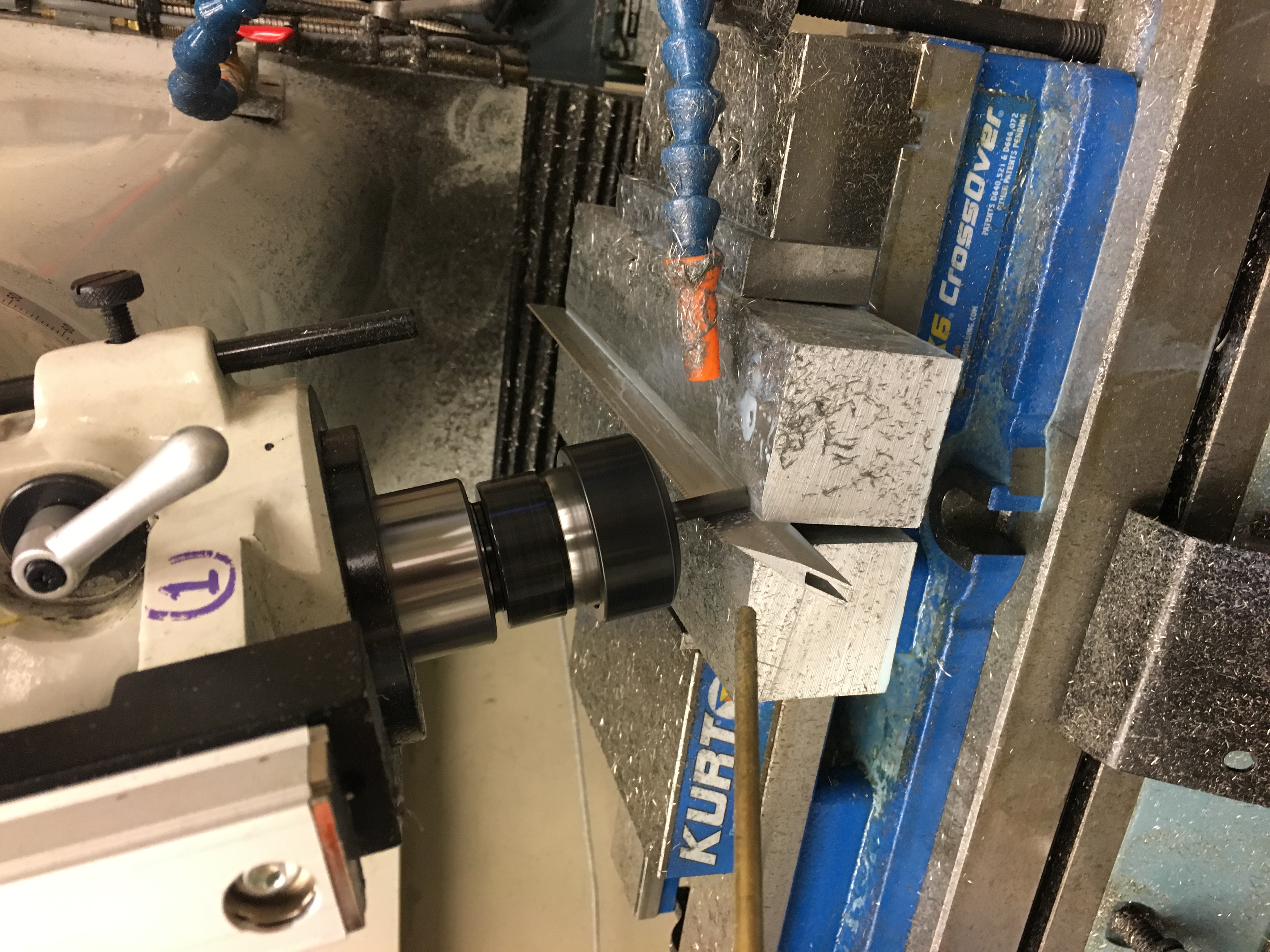
Figure 3: The setup for machining the taper. Note the tilted head, the perpendicular vise, the soft jaws, and the position of the coolant nozzle.
This is the process for a straight end mill.
- Tilt the mill head to 15 degrees.
- Tram the vise perpendicular to the mill table.
- Clamp the LE in soft jaws that extend out beyond the vise.
- Secure the 1/4" Carbide End Mill in the machine.
- Set the speed to 5000 rpm and the feed to 5.4 ipm.
- Set the Z to the final dimension and work the Y in .090" per pass. (Five passes plus a finishing pass)
- Perform a .005" finishing pass.
- Flip the fin and machine the other side.
- Replace the end mill every 2-3 fins.
There are a couple ways to go about this. The first is to use a tapered end mill. This worked well on phenolic. However, now there is a concern that the tapered end mill will not have a uniform chip load and would be a poor choice on stainless steel. The alternative is to tilt the head of the mill or set up an angled work holding.
IV. Finishing
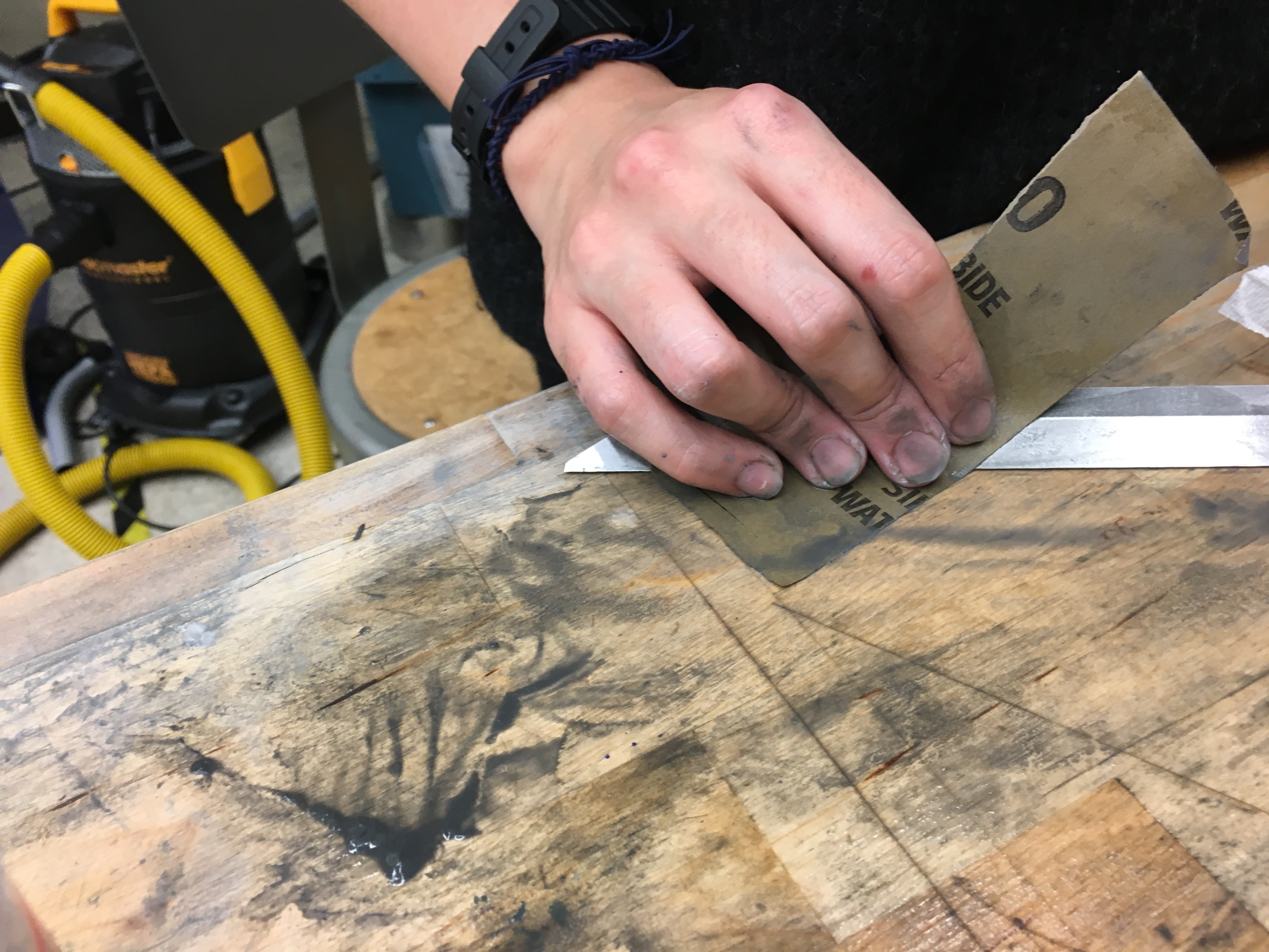
Figure 2: Sanding the LE with 400 grit sand paper. Hold the LE flat against the table so you do not dull the edge or cut yourself.
- If the edge is gummy, clean it with a round file. Be careful not to round edge.
- Sharpen on a wet stone until edge has a .010" radius or less.
- Wet sand to remove tool and scratch marks (Figure 2). A series of 400, 1000, 2000 grit works well.
- Polish with Mothers Aluminum Polish or comparable product.
- Clean and degrease all surfaces with acetone in preparation for bonding with the fin preform.
V. Inspection
- Measure the full length of the leading edge. Confirm that it is within spec.
- Measure the width of the leading edge. Confirm that it is within spec.
- Measure the bluntness of the tip. If it is not within spec, sharpen the leading edge until it is within spec.