Having a basic understanding of solid rocket motors, the next questions to ask ourselves are:
- What shape should our propellant be?
- What size nozzle throat should we use?
To answer these, we must first learn about how our propellant actually burns.
Our propellant is made up of different particles bound together which then burn up and leave the motor as gas. As shown in the image below, the most simple motor we can have is a hollow cylinder with an opening at one end. In this setup, the propellant burns and is expelled through the top.

Although the propellant is made up of different particles, we can think of it as one solid material having the same burn rate everywhere on its exposed surface at a given pressure. As shown below, the propellant burns up overtime until it is eventually depleted.

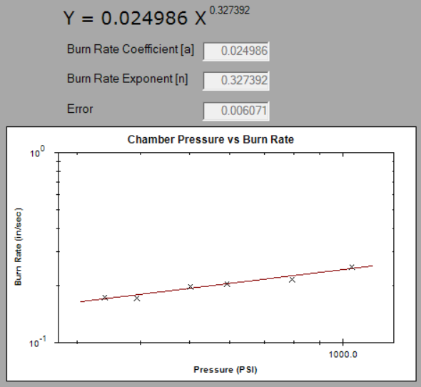
In order to model the rate at which the propellant burns, we assume it regresses according to Saint Robert's burn rate law:

Where: "r" is the linear burn rate, "p" is the pressure, and "a" and "n" are the propellant ballistic coefficient and exponent.
The coefficient and exponent depend on a huge number of factors (such as the actual propellant formula and manufacturing process), so we determine them experimentally. By collecting data on multiple burns of a propellant, we can then characterize it as shown with the graphs below.

The assumptions of this model are:
- All exposed surfaces in the motor regress at the same rate
- Exhaust only leaves the motor through the nozzle
- Choked flow
- Pressure is at a steady state
To find the chamber pressure in a motor, we combine the equations for characteristic velocity and mass flow rate in the motor:


Which then become:

- p is pressure
- A_b is propellant burning area
- A_t is throat area
- c* is characteristic velocity
- rho_p is propellant density
- a and n are the propellant ballistic coefficient and exponent
This is a very important equation, as it allows us to calculate pressure during a burn. Pressure itself is an important value to know for things such as making sure the motor is strong enough to handle the pressure during a burn and knowing the shape of a motor's thrust curve. Also, knowing the pressure allows us to find the burn rate at a given time.
A_b / A_t is also known as "Kn". Once you know Kn, it is trivial to calculate pressure during the burn.
So now we know that Kn can give us pressure, which then gives us the burn rate at a particular time of a burn. But what does the burn rate let us find? Before we answer that, let's first get more into the linear burn rate.
The linear burn rate tells us how much the propellant regresses in a certain amount of time at a specified pressure. We can then apply that to our understanding of how specific propellant grain shapes behave to see what the surface area is after a set amount of time.
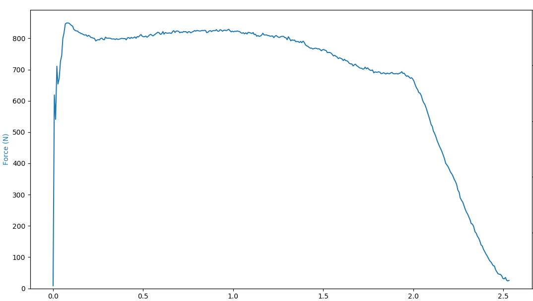
Take for example the BATES grain, which is just a hollow cylinder of propellant:

From its shape, there are two different areas for it to burn. The first is on the inside of it, burning from the inner radius of the cylinder out. The second is on the end of the propellant, burning from the top down.

This burning gives us an interesting pressure/thrust curve. On the one hand, we have an increase of burn area overtime from the expansion of the inner cylinder radius. On the other hand, we have a decrease in burn area overtime for the shrinking of the cylinder's height. However, the result of combining these two conflicting area changes gives us a pretty even curve, since they mostly cancel each other out. The BATES grain in particular is very useful for both its relatively even thrust curve as well as its ease of manufacturing.
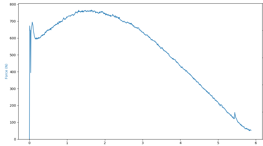
We can also apply our knowledge of propellant burning to other shapes as well. For example, take the Moon Burner shape. It is essentially a BATES grain but with the inner circle offset from the center.

It burns the same way as BATES from the top down, but the way it burns from the inside out differs:

The inner area starts off by expanding (increasing burn area), but then it starts to get cancelled out when the inner circle meets the outer wall. This means that the pressure/thrust increase for a little at the start of the burn, but then decreases overtime as there is less exposed propellant area to burn. Something to note is that the Moon Burner shape in particular is not used very much. Not because it creates a bad thrust curve, but because it is very difficult to implement in practice. For example, it is difficult to create a nozzle in which the propellant doesn't cover up the throat.
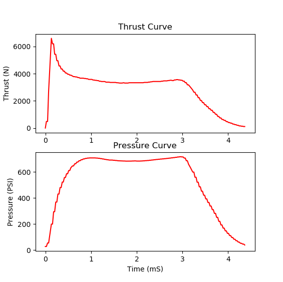
Now that we've gone over the burning of real propellant shapes, we can come back to our question of what burn rate lets us find. Well, it lets us find Kn again! This means that there is a cycle a variables we can find during a burn:

By knowing the Kn at a point of a burn, we can find the pressure. The pressure then allows us to find the burn rate, and the burn rate lets us find the new Kn. This is how openMotor works; it uses the calculated burn rate over a short time to find a new burn area / Kn, continuing the cycle until the propellant is depleted.

In sum, our model takes in propellant geometry, propellant properties, and throat size, goes through the openMotor program with certain assumptions, and then spits out Kn, pressure, and thrust as a function of time for the propellant.
Now that we've talked about modeling propellant grains, it's time to look at some more aspects about designing the grain shape.
First, when designing a grain shape, it is important to make sure its opening is larger than the nozzle throat. Otherwise, the grain will start to act like a nozzle. To avoid this, but still pack as much propellant as possible, it is advisable to "step" the cores. This means that the grain is made up of many sections, and each one has a larger core than the previous one.

Another important thing to keep in mind when creating propellants is erosive burning. This is when a number of factors such as pressure, mass flux (amount of exhaust per time per area that flows through a point along the motor), and propellant strength lead to chunks of propellant tearing off. This causes burn area to spike, meaning the pressure spikes. If there isn't a margin for erosive burning, then a pressure spike could be too much for the motor to handle. Erosive burning can be seen on pressure and thrust curves where there is a large spike that quickly resolves.

When designing/modeling for erosivity, you have to determine the mass flux the propellant can handle without erosive burning, which is typically around 2lb/(in^2-s). If you want to give the rocket a "kick", you can also exceed the limit by a small amount. Finally, it is important to keep in mind that it depends on grain geometry.