Overview
This was a ground test of the Hermes Pathfinder rocket. It occurred on Field A at 3:45 PM on November 10, 2017. It was the first use of the Pyrotechnic Piston to separate the rocket. The piston contained 1g of 4F black powder. The tender descender contained .2g of black powder. The shear pins used were not documented but were likely 2x 6-32 nylon pins and 1x 4-40 nylon pin. The rocket successfully separated, and the tender descender released the main parachute appropriately. After de-integration it was found that the Avionics Bulkhead was seriously deformed. This prevented the planned flight on November 11, 2017 from occurring.

Failure Investigation
Black Powder Sizing Investigation
Upon further reflection, we identified the likely cause of failure. The 1 gram of black powder used in the test was sized for a worst case scenario in which the rocket would not separate until full piston extension. This meant that when the piston was not fully extended, it applied a much greater load (due to a smaller volume causing an increased pressure) to the booster section, which in turn applied an equal and opposite reaction force onto the piston rod and thus the Avionics Bulkhead by Newton's 3rd Law.
We then tried to determine the maximum force felt by the bulkhead:
Step 1: Determine pressure in the piston prior to rod extension
Step 2: Determine force at 0 extension given PSI
Step 3: Evaluate Assumptions
FEA Investigation
Analysis Summary
To perform this analysis, we performed a static load analysis on the Avionics Bulkhead modeled in CAD as of November 16, 2017. Some notable limitations of this analysis are:
- In actuality, this would be better modeled by an impact.
- Since significant deformation was observed (see the image above), it is clear that a nonlinear analysis would be required to accurately model the deformation. The static load analysis was performed to get a basic idea of expected deformation shape and to prove material exceedance at the expected loads.
- The Solidworks part is modeled as one continuous part instead of two separate steps welded together (the weld was not meant to be structural, so this is not the most representative model)
Steps
The steps performed are as follows:
- Aluminum 6061-O was chosen as the material because welding the inner step probably eliminated the material's temper.
- No connections were set.
- The outer step was chosen as the fixed geometry. Technically, the Avionics Bay Coupler only constrains the outer step in one direction (the vertical direction), but the bulkhead is also constrained radially within the Avionics Bay Coupler by the inner step. The bulkhead is not strictly constrained circumferentially except by friction after putting the Avionics Bay Coupler under compression (in an ideal execution of the design, which was not necessarily achieved for this test): this is irrelevant to the load applied.
- 1750 pounds were applied to each of the two bolt holes used during the test. Technically, a more accurate representation would be to include the bolts in the model. Using just the bolt holes isn't perfectly accurate because the load was actually applied to the outer side of the bulkhead by the heads of the bolts rather than in the bolt holes (which were not threaded).
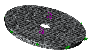
- The finest possible mesh was generated. An image is featured below, which also summarizes the previous steps.
Results
As the following figure shows (in particular, pay attention to the red arrows indicating yield strength vs. stress experienced by the material), the bulkhead saw serious material exceedance.
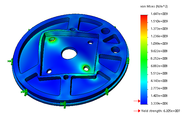
Additionally, the deformation shape shown is consistent with a 2-bolt load application (note: the magnitude of deformation shown in Solidworks is generally exaggerated from simulation results for viewing purposes, though it happens to look fairly realistic here).
Media