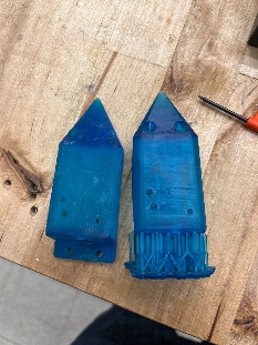
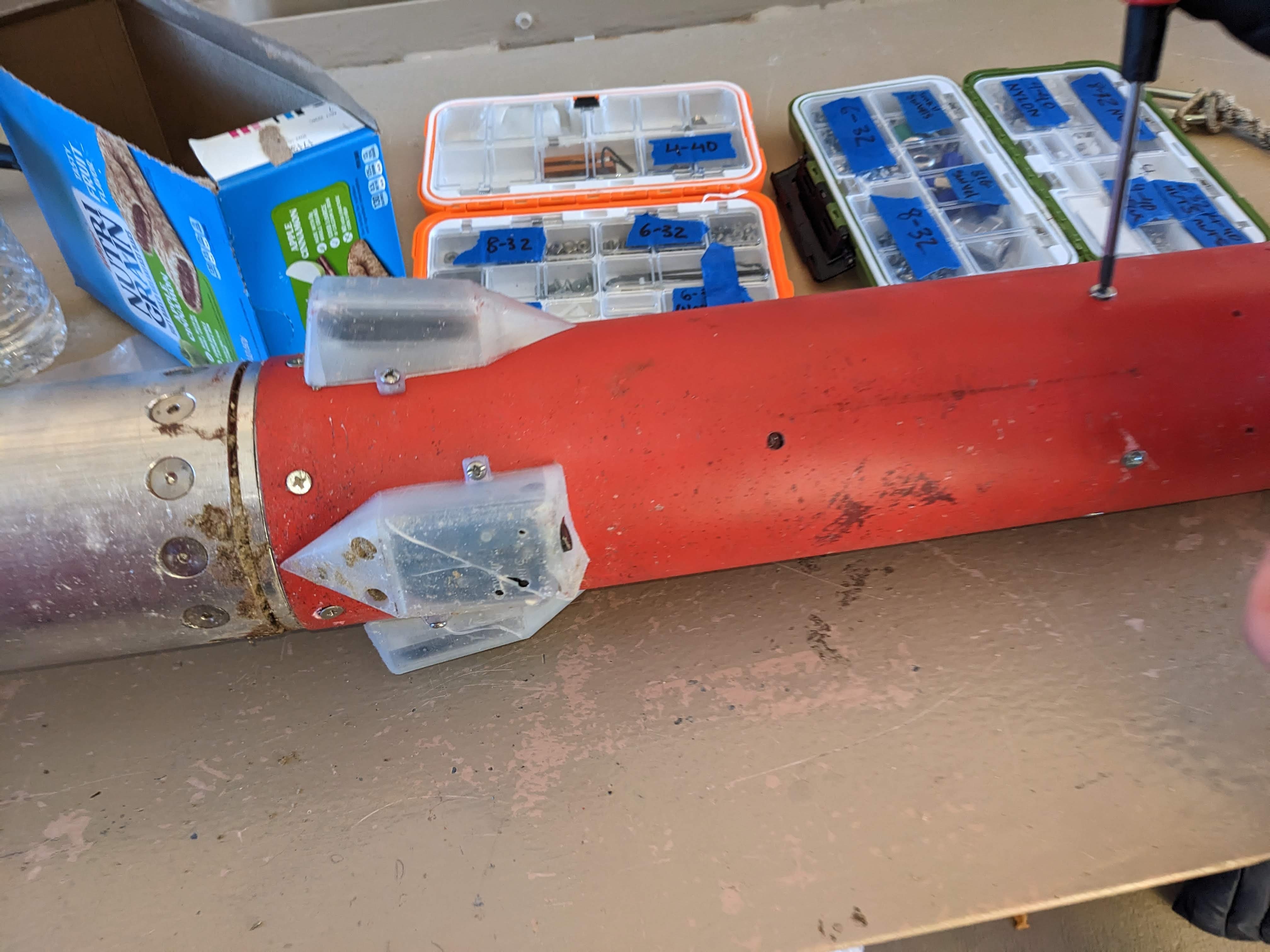
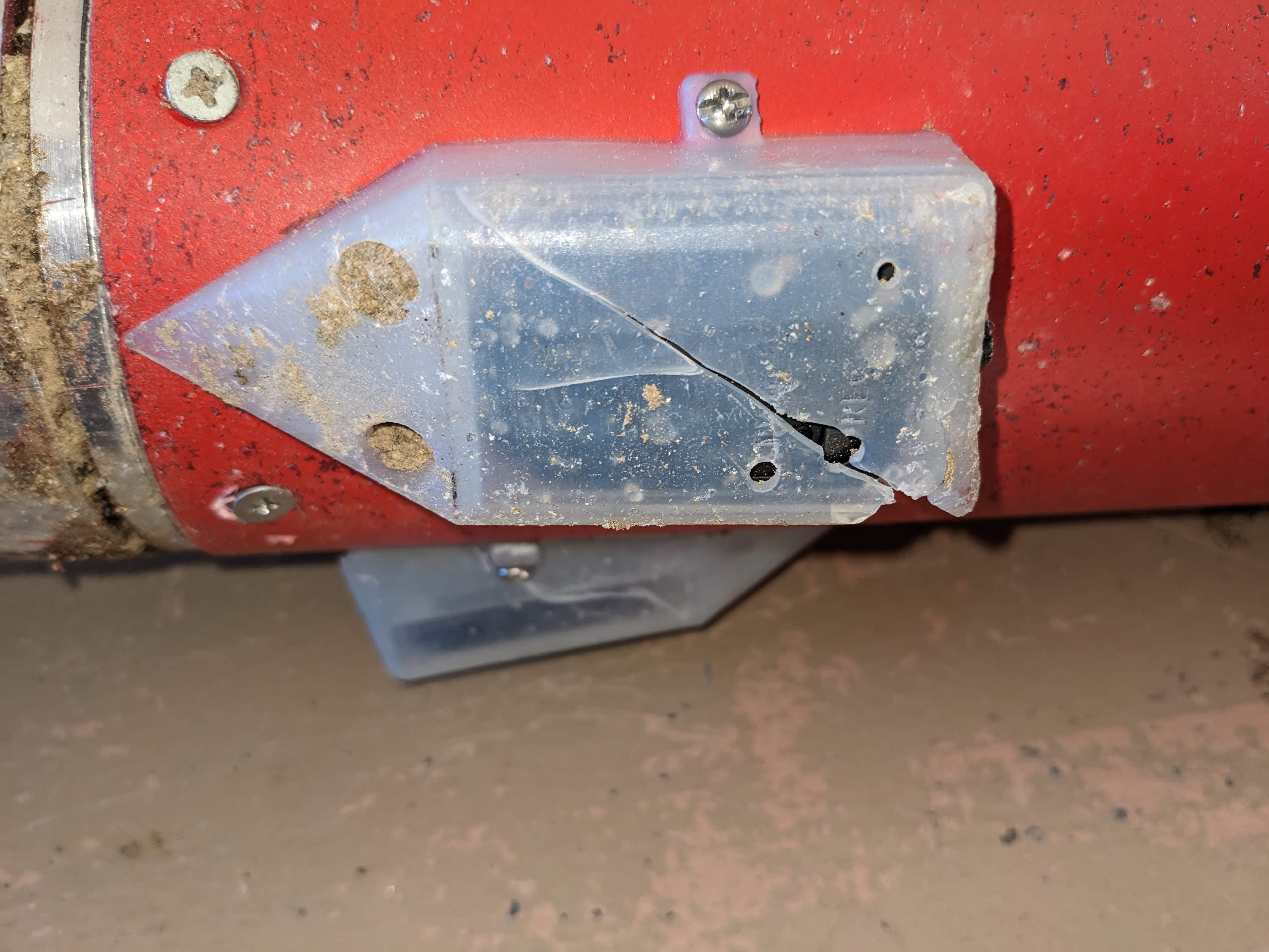
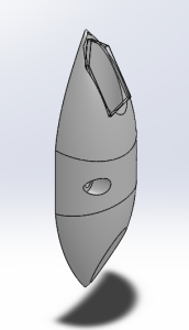
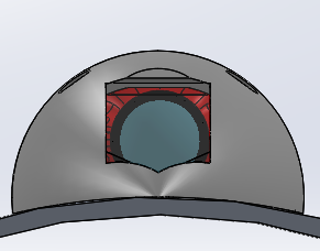
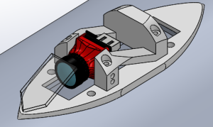
New exterior flight camera housings (known here as "aeroshells") were designed and fabricated for projects Medusa and Prometheus (Fall 2023 - Spring 2024). The Prometheus aeroshell consists of a sleek, lightweight, and thermally insulating fiberglass shell mounted to a 3D printed PLA mounting frame. A piece of high-temp, high-strength glass is embedded into the shell to allow the camera a clear view. Compared to its predecessor from Project Phoenix, the overall design offers much-improved aerodynamic and heat-shielding capabilities, as well as eliminating the need for separate upward- and downward-facing shells. The aeroshells flew successfully at the test launch of Prometheus, with all four shells returning undamaged and high quality footage recovered from the installed flight camera.


Above are photos of several flight aeroshells taken shortly after Prometheus test launch.
Page Contents:
- Background
- Research and Preliminary Designs
- Design Development
- PMTS Design
- Overview
- Manufacturing Process
- Results
- Future Plans
Background
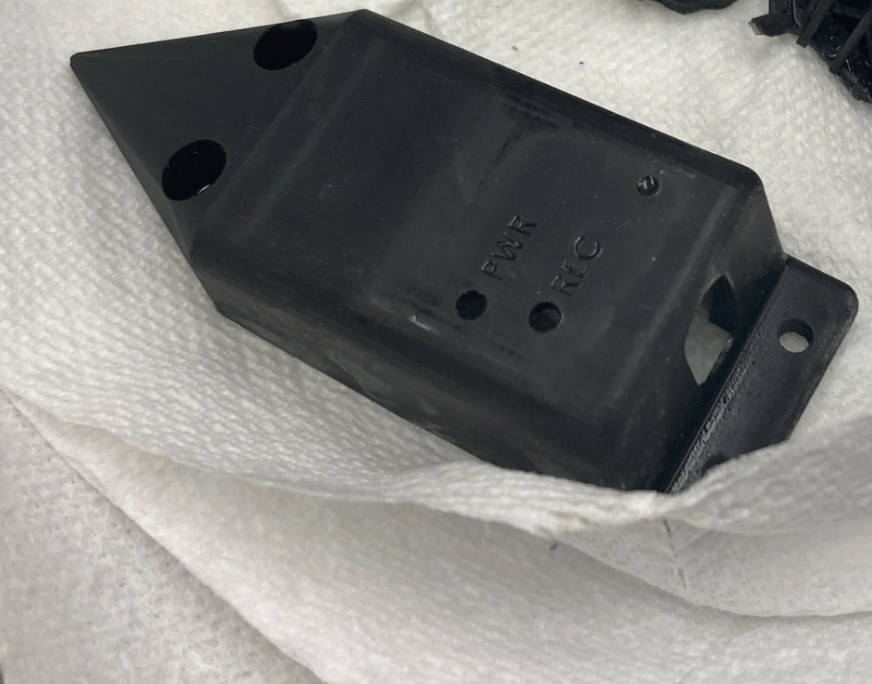
An initiative to redesign the aeroshells was made after the launch of Project Phoenix and the discovery of several issues with the existing aeroshells.
These were the Phoenix aeroshells in their development stages (images from 2022): 
And images from Phoenix launch, after recovery (2023):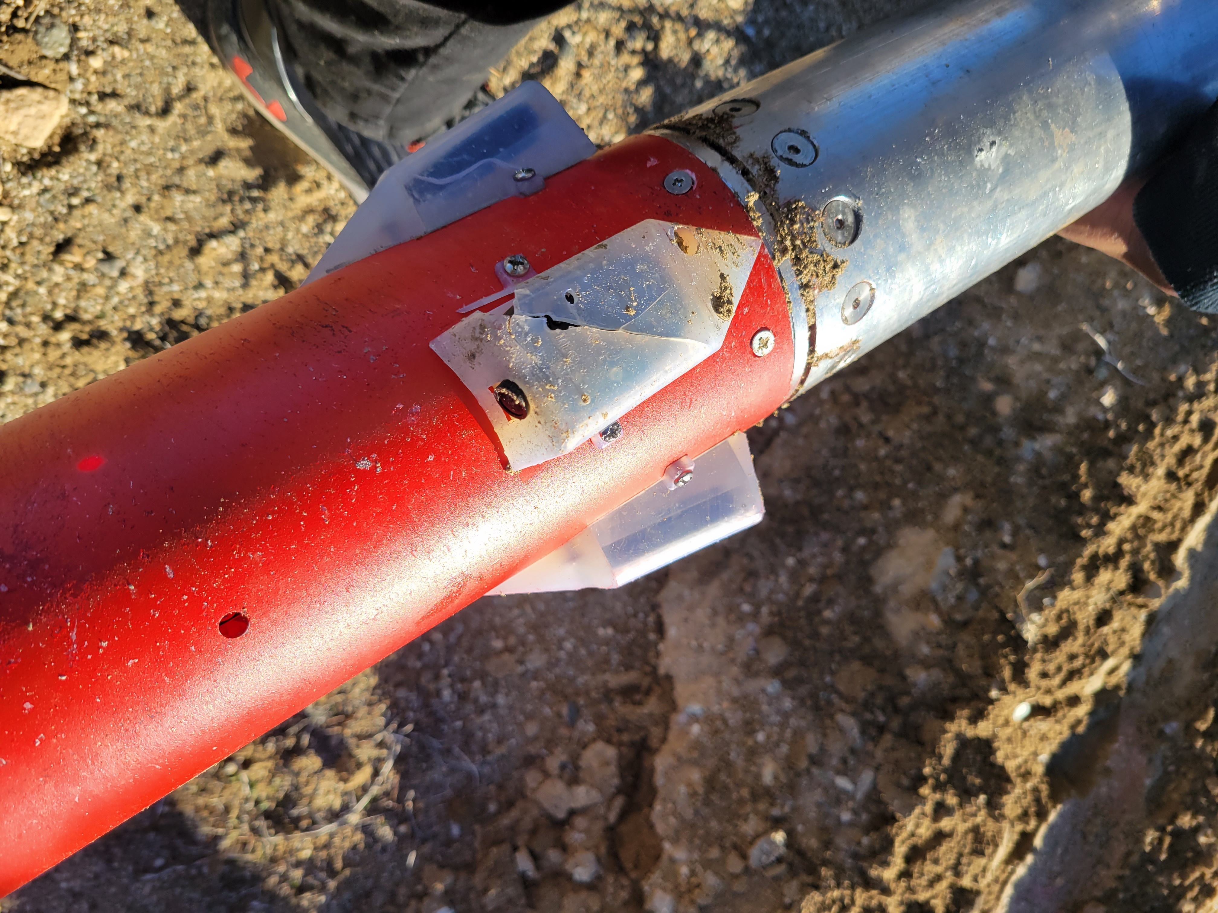
Two designs were made in parallel, one to hold the Runcam Split flight cameras and another to hold 808 Keychain Cameras. These aeroshells were 3D printed from SLA resin and bolted onto the mission package tube. After launch, multiple issues were identified in this design:
- Many of the cameras turned off on the pad, so they did not record footage. Overheating was identified to be the most likely cause.
- The cameras were turned on and the rocket left on the pad for an unexpected length of time (~1 hour).
- Since launch happened in January, the temperature outside was still chilly. The camera generates heat while operating, so the overheating most likely happened because its own heat was trapped inside the shell.
- They may have also absorbed heat from the warm sunlight.
- After recovery, some of the aeroshells were noticed to have a gummy or sticky surface texture.
- After launch, avionics placed another set of aeroshells outside in the sun, with cameras inside them. The experiment recreated the camera shutoff and sticky texture from launch.
- The stickiness could be due to improper curing of the resin print.
- Could also have been softening from in-flight heating (air friction, stagnation).
- The aeroshells required access to the inside of the tube to mount, as well as space for nuts on the interior. This can obstruct the AV bay from being inserted into the rocket, and requires the aeroshells to be integrated before anything else gets put inside.
- The shape is bulky, with many corners, flat faces, pockets, and protrusions that disrupt airflow. Phoenix had a significant (~10,000 ft) discrepancy between predicted apogee and actual apogee. The shape of these aeroshells likely exacerbated coning and increased drag on the rocket in a way that was not predicted in simulations.
- The aeroshell cracked on impact with the ground. This is fine, we don't need to design things to survive hitting the ground.
With the new design, we hope to fix the issues of the previous while improving the aerodynamic performance and thermal robustness.
Research and Preliminary Designs
In Spring 2023, Summer Hoss '23 led aeroshell redesign sessions. The goals were to conduct research and establish a preliminary design.
- Research was conducted to narrow down a set of materials that provided sufficient thermal insulation while being reasonable to buy and fabricate with. These materials ended up being:
- Nylon 66 3D print - somewhat more heat-resistant than PLA or SLA, though still runs the risk of softening.
- carbon fiber - very heat-resistant. Pure carbon fiber may soften from heat, depending on the thickness. May be difficult to work with, given the size of the aeroshells and the team's level of experience with composite materials.
- Other composite materials - same as carbon fiber, but the team has limited experience with it.
- Some design ideas were generated:
- Using the shape of the existing but unused aeroshell CAD model made by Chad Meier '23.
- This idea was implemented, shown in the next two images below.
- Incorporating a mirror so that the camera can be oriented differently from the direction we want a recording of.
- In-flight vibrations were found to not interfere with this type of design.
- This idea was initially implemented, then removed due to the complexity it introduced.
- Incorporating air pockets for increased insulation
- Using aerogel
- It's an expensive and unfamiliar material
- We can achieve sufficiently high performance using less complex materials
- Using honeycomb structures such as Nomex
- Adds a lot of thickness
- Using aerogel
- Relocating the onboard cameras to inside the rocket
- Interior flight cameras are more aerodynamic
- Consequently, it's a much more common design
- It's difficult to buy or find examples of exterior flight cameras for high-powered rockets. Most, like the Estes AstroCam, are made for small model rockets.
- People really wanted our cameras on the exterior, for the view.
- Using the shape of the existing but unused aeroshell CAD model made by Chad Meier '23.
In Fall 2023, the design of the aeroshells became a collaborative effort between the Medusa Aerodynamics and Prometheus Structures subteams. Interested members cooperated to produce rough designs for the Medusa conceptual design review (CoDR) and preliminary design review (PDR), slides linked. These were designed for the 808 cameras, to be made with T300 standard modulus twill weave carbon fiber and withstand a maximum in-flight temperature of 1300°F (Note: this temperature requirement lowered as design changes were made to the rocket). A negative mold would be made for them using foam and a CNC router. After preparing the mold, the carbon fiber would be laid up and vacuum bagged. Ideally, the part can be left to cure in a composites oven so that it attains a higher operating temperature. We obtained access to Prof. Zachary Cordero's composites oven in his lab for this purpose. Post processing would be done to create holes for mounting these to the mission package tube.
For the Medusa conceptual design review (CDR), the development of the aeroshells shifted to be more the responsibility of the aerodynamics subteam. Design changes were made so that the shells could be more easily fabricated and design details were further developed. Thermal simulations were attempted, but unsuccessful. The slides are attached here.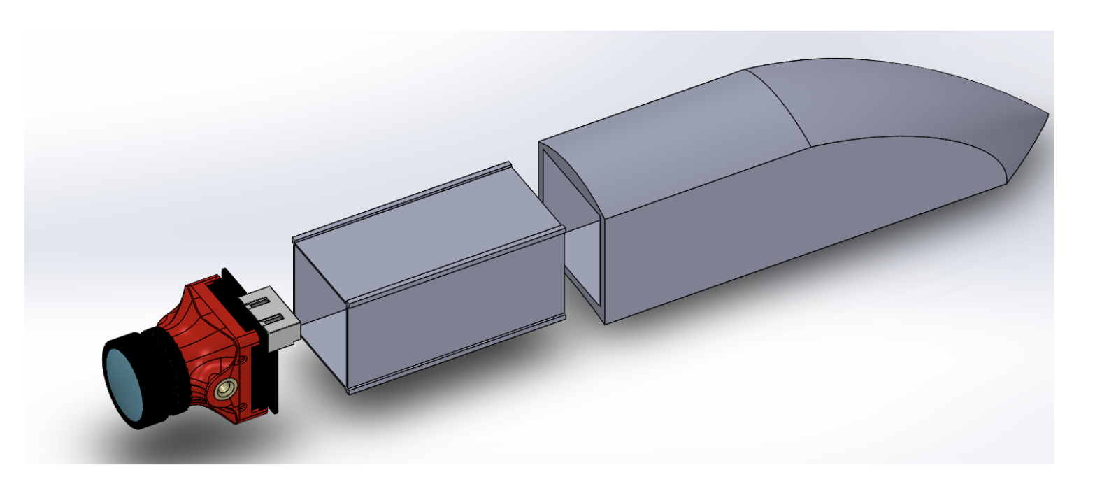
This simplified design involves two plies of carbon fiber over a 3D printed frame, with heat-resistant paint applied to the exterior as an ablative coating.
Design Development
After the cancellation of Project Medusa, the remaining members of the Medusa Aerodynamics subteam (Vealy Lai '26, Conrad Casebolt '26, Ethan Wong '26) were absorbed into Project Prometheus and turned their primary focus to developing the aeroshells. With renewed efforts, a clearer design process was defined for this component.
Design Goals:
The new aeroshells should be able to protect the flight cameras from physical and thermal damage from the moment the rocket is powered on to the moment it hits the ground. This means that the interior of the aeroshells should stay below 50°C at all times, even with ambient temperatures as high as 100°F, stagnation temperatures up to 1000°F, and heat emitted from the operating camera itself. The aeroshells need to keep themselves and the cameras securely fixed to the rocket, so they and their connectors must be able to withstand all in-flight forces with a safety factor of at least 1.5. The shell must also provide a clear and sufficiently large viewing window so that all motor ignition, stage separation, and deployment events are visible in the camera recordings.
Design Requirements:
The aeroshells, of which there are four (4), shall be mounted to the outside of the mission package tube on each stage. Each aeroshell must contain and protect a camera which records the flight of the rocket. The upward facing aeroshells shall capture the deployments of the recovery systems. The downward facing aeroshells shall capture the ignitions and staging.
The aeroshell design must be streamlined in shape to minimize drag.
The upward-facing and downward-facing aeroshells must be aerodynamically similar to the greatest extent possible.
The aeroshell shall thermally insulate the camera from both the external thermal loads of in-flight drag and the stagnation temperature experienced by the rocket.
The camera must not overheat inside the aeroshell when left on (includes pad time and flight time).
In-flight forces were determined to be negligible compared to the strength of the shell materials and connectors.
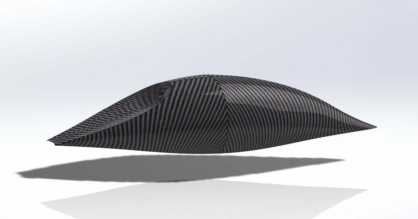
Aerodynamic Design
The aeroshell is streamlined on both ends. Its diameter is only minimally larger than the Foxeer Camera which it houses.
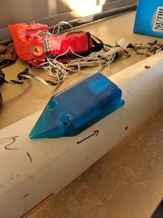
(Previous Iteration of Aeroshell IAP 2024)
Aerodynamic Testing
CFD analysis will be performed in the future.
- Update 5/5/24: No aerodynamic or thermal simulations have been conducted on the aeroshells
Manufacturing (Nov. 2023)
The aeroshell mold is 3D printed using PLA. A piece of heat resistant glass is cut to the required shape. Three layers of carbon fiber are attached to the exterior of the mold with an epoxy layup using a vacuum bagging technique.
- We performed this procedure for two first-iteration aeroshells, but the carbon fiber did not bind well to the outside of the aeroshell. It is difficult to map the planar sheet of carbon fiber onto the steeply curved exterior of the aeroshell. As a result, a negative mold may be used in the next iteration.
Thermal Testing
In order to recreate the thermal loads experienced by the aeroshell, the aeroshell will be exposed to the stagnation temperature of 350°F using a heat gun for one minute. It will be mounted to a piece of fiberglass to emulate the exterior of the mission package tube.
- Thermal testing concluded that fiber glass is a better choice of composite for the Aeroshell compared to carbon fiber. An identical fiber glass aeroshell maintained a lower internal temperature compared to a carbon fiber counterpart.
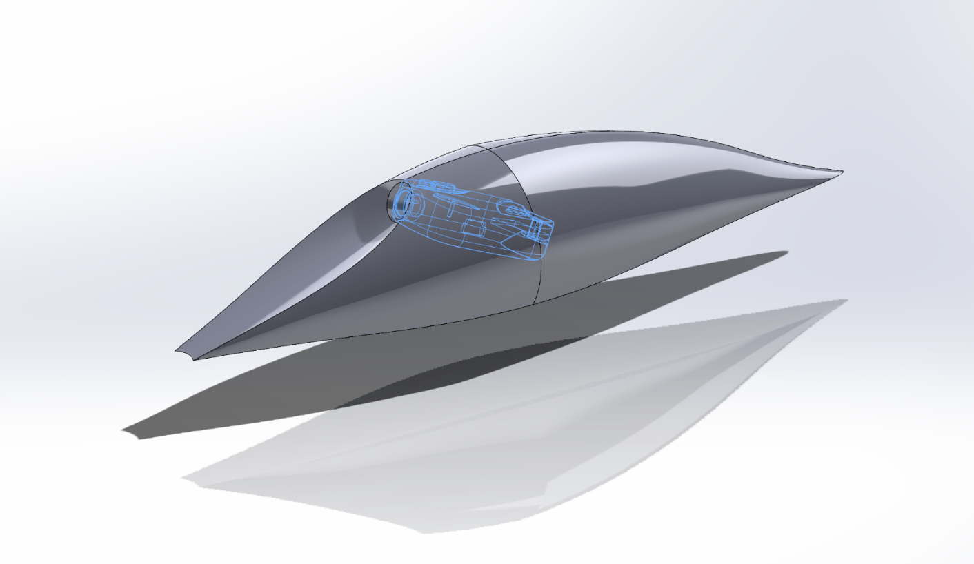
Current Design (April 2024)
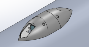
Overview
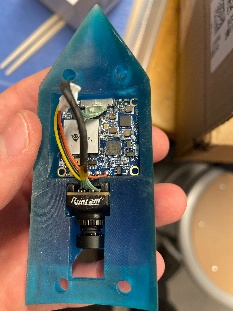
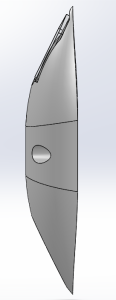
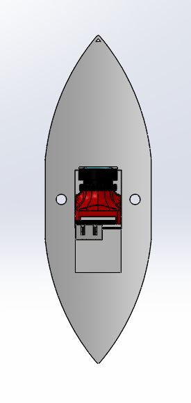
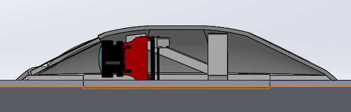
The current design features two separate parts: The Shell and the Skeleton. There is also a glass panel attached to the end of the viewing aperture and camera.
Shell
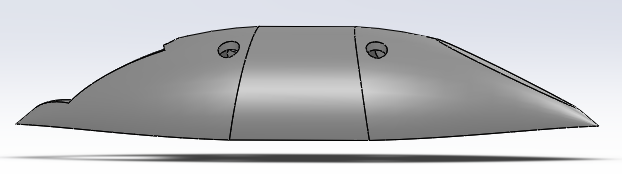
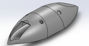
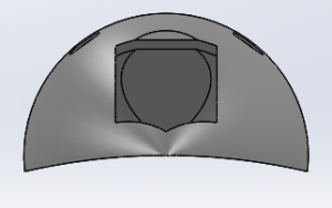
Skeleton
Manufacturing
Due to the non-planar shape of the shell, the only viable method of manufacturing is to use a negative mold with composite-epoxy layups sealed in a vacuum bag. The general overview of the process is as follows:
- Print a negative mold of the shell using PLA.
- Perform three consecutive epoxy layups in the negative mold using three layers of fiber glass composite, abiding by the general procedures of epoxy layups.
- Vacuum bag the negative mold and hold near/complete vacuum for 24 hours using a vacuum pump.
Detailed Manufacturing Instructions
Materials/Equipment Master List
- 3D Printer
- Sandpaper
- Acetone
- Wax
- Gloves (and optionally a mask)
- PVA release film
- Vacuum bag plastic
- Vacuum tape (double sided)
- 1x1" squares of heat resistant glass
- Glass scorer (Metropolis has some)
- Glass-breaking pliers (Metropolis has some)
- Thin-woven fiber glass sheet (Gelb Lab)
- Woven fiber glass sheet (Gelb Lab)
- 2-part epoxy resin
- Peel ply (Gelb Lab)
- Breather
- Vacuum pump
- Four (4) M2 screws
- Four (4) M3 or 1/8" screws and corresponding nuts
- Dremel with cutting and sanding wheels
Obtaining and 3D Printing the Negative Mold
Materials: 3D Printer
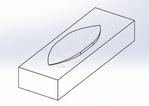
- Obtain CAD file of a negative mold of the exterior shell (YouTube tutorial for creating a negative mold linked here; CAD for this iteration of the Aeroshell has already been developed).
- Convert the CAD to a .STL file. Print the negative mold on a 3D printer using low infill (10-20%) and material PLA.
Mold Preparation Steps
Materials: Sandpaper, acetone, wax, gloves, mask (optional), PVA release film
- Sand down the inside of the mold to get rid of any burrs and smooth out surfaces. A few minutes of sanding will suffice.
- Remove all the dust from the inside by washing and drying or wiping with acetone.
- Rub down the inside and top planar surface of the mold with wax until glossy and smooth. A pea-sized portion of wax should be sufficient.
- The wax is toxic if ingested, so wash your hands after use.
- Put gloves on (and optionally a mask) and move to a well-ventilated area, preferably outside. Apply a coat of PVA release film by gently rubbing it in a layer over the wax. A bottle cap of PVA should suffice.
- Recommended to do this outside and stand upwind because plastic fumes are not good to breathe in.
- Visually, the layer should appear shiny.
- Optionally: If you want multiple coats, wait until the first coat dries (drying time listed on the bottle).
Vacuum Bag Preparation Steps
Materials: Vacuum bagging film, vacuum seal tape
- Cut out some vacuum bagging film the size of your part(s), leaving generous margins.
- If a clean glass surface is available, apply mold release to it and then use the glass as the bottom side of the bag.
- Doing this can help eliminate the sideways compression that can be introduced by a full bag. This can affect the quality of some layups, depending on how the compression should (and shouldn't) be applied.
- Otherwise, cut a big piece of film and fold it in half to form the two sides of the bag.
- Use vacuum seal tape to seal two sides of the bag together. Make sure the seal is smooth and free of wrinkles and leaks. The remaining side will be sealed once the part is inside.
- If the part to be vacuumed is not flat, make the top layer of the bag longer and fold some pleats into it before sealing. This will ensure the film has enough slack to conform to the geometry of the part.
- Look up video demonstrations of this! There are many techniques for good vacuum bag preparation that can be learned that way.
- If a thru-hole connector is available for the vacuum pump, cut a hole in the top of the bag for it. Attach the pump that way.
- Otherwise, attach a hose to the pump and tape some breather around the end to prevent epoxy from getting inside (just in case). Use vacuum seal tape to seal the hose into one side of the bag.
- Make sure the hose is not blocked when the bag is fully sealed.
- If a clean glass surface is available, apply mold release to it and then use the glass as the bottom side of the bag.
- Cut out some vacuum bagging film the size of your part(s), leaving generous margins.
Epoxy & Fiber Glass Layups
Do in well-ventilated area.
Materials: Vacuum Pump, thin-woven fiber glass sheet, thick-woven fiber glass sheet, 2-part Epoxy Resin, peel ply, breather, gloves, mask/respirator
- Cut one rectangle of thin-woven and two rectangles of regular-woven fiber glass (per Aeroshell) in a sufficient size to fit inside the negative mold cavity.
- Cut a layer of peel ply slightly larger than the fiber glass rectangles.
- Cut a rectangular layer of breather roughly equal in size to the upper planar face of the negative mold.
- Put on gloves.
- Weigh the fiberglass fabric on a scale. Measure out an amount of epoxy and hardener in the appropriate mixing ratio, with a total weight equal to that of the fabric to be laminated.
- West Systems 105 Epoxy and 206 (slow) Hardener were used.
- When ready, slowly mix the resin and hardener together until uniform. Try to avoid introducing bubbles.
- Be conscious of time. This epoxy has a pot life of about half an hour, meaning that at that point it can become too viscous to apply. Note that working time is a different specification that indicates when the epoxy will start curing, typically well past its pot life.
- It can help to mix batches of epoxy and layup one aeroshell at a time, though you will want to vacuum bag them before the epoxy begins curing. Having multiple people working in parallel is ideal.
- Be conscious of time. This epoxy has a pot life of about half an hour, meaning that at that point it can become too viscous to apply. Note that working time is a different specification that indicates when the epoxy will start curing, typically well past its pot life.
- Coat fully the inside of the negative mold with a layer of epoxy, using about 1/3 of the total epoxy allotted for one Aeroshell.
- Lay the thin-woven layer of fiber glass into the negative mold cavity. Gently press/move the layer until it contacts the surface of the cavity and nearly every point.
- This process is difficult and requires practice. Tips:
- Start from the deepest point in the mold.
- Provide excess material at first and flatten it out later.
- Don't overstretch the material.
- Use nails to lightly fit the sheet into sharp corners.
- This process is difficult and requires practice. Tips:
- Repeat the above process two more times but using the regular-woven sheets of fiber glass cut out earlier and 1/3 of the remaining epoxy each time.
- Press the precut sheet of peel ply into the mold covering all of the fiber glass.
- Place the breather on top of everything else.
- When this is done proceed quickly to the following section.
Holding a Vacuum
- Put the mold and layups into the open end of the previously prepared vacuum bag.
- Close the vacuum bag.
- Turn on the pump. The bag should quickly pull a vacuum and the shape of the negative mold will become visible.
- Not recommended but sometimes necessary: The vacuum can be tested by turning off the pump briefly and observing how quickly air is let back in. Sometimes the pump has trouble turning back on if this is attempted.
- If the bag is not holding a vacuum well at all, the manufacturing process may be compromised.
- Not recommended but sometimes necessary: The vacuum can be tested by turning off the pump briefly and observing how quickly air is let back in. Sometimes the pump has trouble turning back on if this is attempted.
- Leave the pump on for 24 hours.
- When the process is complete, leave the pump on and cut a large hole in the bag near the pump tube. Allow the pump to run freely (not pulling vacuum) for a few minutes before shutoff.
Removing the Aeroshells from the Mold
- This process can be a little bit tricky, so try not to damage the Aeroshells in the process.
- Separate the shells from the mold. There is no real procedure, so use the following tips:
- Try to separate by pulling up on the corners of the peel ply or the fiber glass itself.
- Use a blunt and thin tool, like a skinny screwdriver, to carefully disconnect the edges of the shell from the mold.
- Support the sharp corners at the edges of the cavity of the shell as you pull the shells out.
- You will visibly see the areas which are free of the mold. Use these to continue to make progress on getting the shells out – they won't come out in one piece.
3D Printing the Skeleton
Materials: 3D Printer
- Convert the CAD file into a .STL file. Material as PLA and 0.2mm thickness are sufficient.
- When slicing the file, change the following settings:
- The side which touches the MPT should be normal to the print bed (even though it is not flat).
- Infill should be >70%
- Supports set to ON EVERYWHERE.
- Brim set to ON.
- Make sure to remove all the excess material from the screw holes and supports after printing.
Cutting the Aeroshell to the Proper Size
Materials: Skeleton, four (4) M2 screws, Dremel with cutting and sanding wheels
- Place the fiberglass shells over the 3D printed part.
- Mark the locations of the screw holes and drill through the fiberglass.
- Screw the fiberglass onto the 3D printed part, then and trace around the edge and trim it to size with a Dremel cutting wheel. A sanding wheel can be used to even out a rough cut.
- Note that the fiberglass can deform slightly after being screwed in, so the edge may be uneven if the shell is trimmed based on how it sits without the screws it.
- Stay safe! Wear proper PPE to avoid breathing in the dust.
Glass Pane
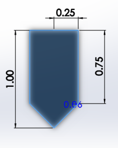
Materials: 1x1" square of heat resistant glass, marker, glass scorer, glass-breaking pliers, sandpaper
- Break the 1x1" square in half into two pieces.
- Use a marker to draw a line divided the glass into two equal rectangles. Score along the midline on both sides of the glass.
- Carefully break the glass in two using the glass breaking pliers. A useful technique is to hang the excess glass corner over an edge and repeatedly hit (rather softly) the overhanging piece using the glass-breaking pliers.
- In theory, each glass panel should yield two useful glass pieces.
- Cut the glass into the correct shape to fit into the aeroshell.
- Use a marker and ruler to trace the correct five-sided shape on the 0.5x1" glass panel
- Score the glass along the lines using a glass scorer on both sides.
- Carefully break off the excess glass using the glass-breaking pliers.
- Sand down the edges until the desired dimensions are achieved.
- Caution: Don't scratch up the glass surface through which the camera is viewing.
- Mix some epoxy and apply it to the edges of the aeroshell where the glass should sit. Lay the glass down flat, and let dry.
- Break the 1x1" square in half into two pieces.
Results
These Aeroshells flew on the Prometheus test flight in April 2024. All four remained intact through subsonic flight speeds and an estimated apogee of 5,000 feet (**double check this CC 5/16/2024). Only one Aeroshell carried a live camera, which captured valuable footage of the booster recovery system deployment. The camera did not overheat during flight or on the pad.
A whistling sound was recorded on the camera audio as the rocket ascended. It is unknown whether this sound is produced by air flowing past the aeroshell or another part of the rocket.
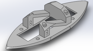
Integration
The two-piece approach necessitates the following integration steps:
- Mount the skeleton to the mission package tube using four (4) M3 or 1/8" screws and corresponding nuts, with the nuts inside the MPT.
- Attach the camera to the skeleton and connect the camera to the avionics bay.
- Mount the shell to the skeleton using four (4) M2 screws.
Future Plans
Future Design Improvement Ideas (as of May 2024)
- The exterior screws should be angled to keep the screw heads normal to the face of the exterior shell.
- The exterior screws are currently threaded directly into the PLA of the skeleton. A future design should add a threaded metal component on the skeleton in order to better secure the assembly together.
- The aerodynamics of the up- and down-facing aeroshells are similar but not identical. Perhaps a new glass shape could be designed, or non-planar glass could be used.
- The cross-sectional profile could be further reduced by using a parabolic shape instead of circular, although a redesigned shell must retain adequate room for the structural supports of the skeleton.
- The field of view could be increased.
Future Manufacturing Process Improvements (as of May 2024)
- The skeleton could be printed in two parts to get rid of the roughness on the face bordering the MPT.
- ** Link to AUR Aeroshell page