Part | Component Status | Responsible Engineers |
|---|---|---|
| Sustainer Avionics Tower AV000 | Manufacturing Prep | Laura Schwendeman 2023 Quin Bowers 2023 |
Purpose/ description:
A structure meant to house the avionics equipment for the Phoenix sustainer.

Requirements:
1.1. Must be able to survive acceleration of the rocket (196 m/s^2)
1.2. Must be able to survive the vibrations of the rockets
1.3. Must fit within mission package tube
1.4. Must hold all required avionics components and allow them to function
1.5. Must be relatively easy to integrate and attach into the rocket
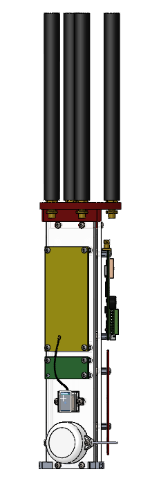
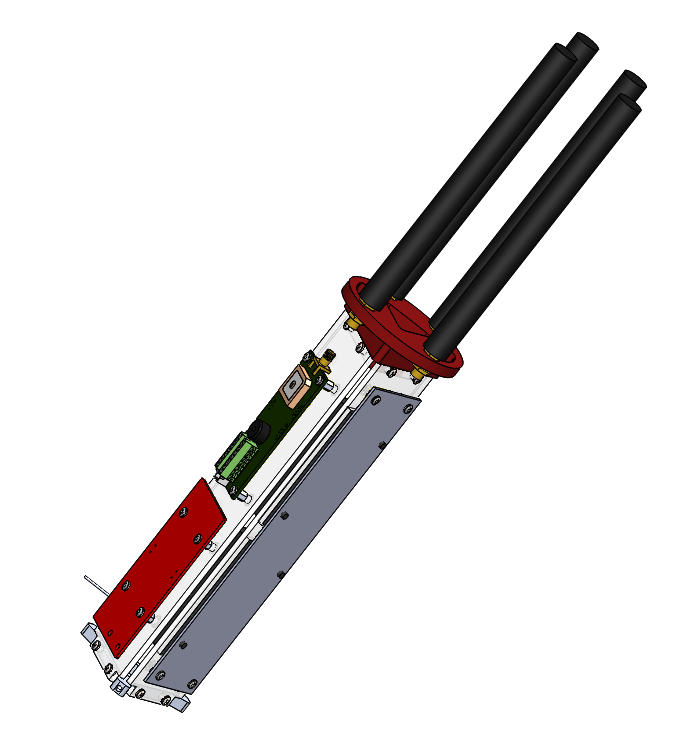
The Avionics Tower is composed of many elements and houses much of the avionics equipment required for flight. Its design was inspired by Hermes AVTowers, which housed electronics on a set of panels. The Sustainer Avionics Tower uses 3 panels.
The Sustainer Avionics Tower is composed of 5 main subcomponents: The antennae and antenna mount, the 3 panels, and the Avionics Tower Mount.
Estimated Weight (based off of CAD Model): 583.98 grams, approx. 1.2875 lbs
Design Brief:
We began this process mainly building off the Hermes III AV Tower. It was there that we got the idea of a prism of some sort. The much smaller diameter of the Hermes sustainer meant that we could have three faces at most, so we spent several sessions deciding whether to choose that or a simple slab. In the interests of saving height, we decided to go with the triangle and see whether we could fit all of the avionics components in such a structure.
Three main things drove the design: the curvature of the rocket, the avionics parts we needed to work around, and the piston. We attempted to fit the AV Tower around the piston (as we did in booster), but found it impossible with the available space. Furthermore, the curvature of the airframe meant we generally could not fit two avionics components side by side, even if there was technically space on the board.
Finally, our last conflict was with the antennae; to reduce interference, they need to be as far away from both each other and other metals (see avionics for more details), which was why they were not allowed to overlap with the piston.
For a more detailed description of the design considerations for each part of AV000, see the various sections below.
CAD Design:

Antenna Mount:
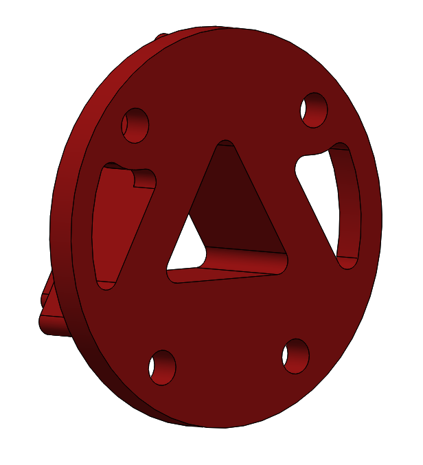
The Antenna Mount serves two purposes. It acts as a cap to attach and constrain the 3 panels with all of the boards, and it also serves as a mount for the 4 antennae that communicate with avionics components.
The antenna mount was designed to keep the antennae as far apart as possible to reduce signal interference. Antennae experience interference from other antennae broadcasting on the same wavelength, as well as nearby metal objects. This is why the antennae were not permitted to overlap with the piston. By sitting on top of the sustainer AV tower, the antennae are also as far away as possible from interfering metals in the motor.
Manufacturing: 3D print from PLA, using stl from cad model.
Drawing: AV002 Top End Cap + Antenna Holder.PDF
AV101, AV201, and AV301 Panels:
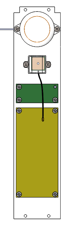

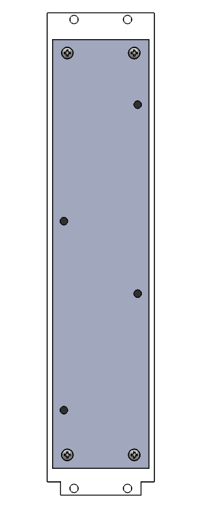
These polycarb panels provide mounting holes for pcbs and other flat components. These are the most important parts of the tower, held together and attached to the rocket by the others.
Manufacturing: Waterjet polycarb
- Position polycarb in Waterjet bay
- Restrain polycarb from the sides using additional metal, secured using clamps and weights
- Ensure water level is below polycarb sheet to prevent it from floating
- Zero Waterjet, begin cutting
- pause the machine and remove panels each time one is cut to prevent them from falling.

Drawings: AV101 (Pyxida Panel).PDF
AV301 (Raven + Dennis Panel).PDF
New End Cap (Avionics Tower Mount):
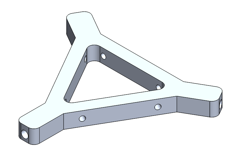

The Avionics Tower Mount affixes the entire Avionics Tower to the airframe. It must support the forces exerted by the weight of the avionics tower.
The only forces that this structure needed to withstand was the weight of the avionics tower above it at 20g. As such, the design of this structure was meant to optimize a reduction in weight.
Manufacturing: From aluminum. Waterjet to size, then use the radial indexer for the radial holes and a drill press (?) for the panel mounting holes, and finally tap all screw holes appropriately.
Drawing: AV005 New End Cap.PDFIntegration:
Sustainer Avionics Integration
Summary Tables:
These tables below offer some summary information about the parts in the Sustainer AV Tower
Manufactured Elements of the AV Tower:
Part Name | Material | Manufacturing Method | Cost |
AV002 Top End Cap + Antenna Holder | ABS/PLA | 3D print | 0 |
AV101 Pyxida Panel | Polycarbonate | Waterjet | |
AV201 Telemega Panel | Polycarbonate | Waterjet | |
AV301 PMS Panel | Polycarbonate | Waterjet | |
AV005 New End Cap | 6061-T6 Aluminum | Waterjet + Lathe + Drill | |
AV104 GPS Holder | ABS/PLA | 3D print | 0 |
AV105 Beeper Holder | ABS/PLA | 3D print | 0 |
Avionics Components housed on the AV Tower:
Part Name | Quantity | Material | Cost | Link |
AV004 Antenna | 4 | ---- | ??? | |
AV003 SMA Passthrough | 4 | brass | 8.10$/unit 31.40$ total | |
AV302 Raven | 1 | --- | ??? | https://www.featherweightaltimeters.com/raven-altimeter.html |
AV303 Dennis | 1 | --- | ??? | See Avionics Wiki |
AV105 Adafruit Passive GPS | 1 | |||
Beeper | 1 | http://www.com-spec.com/rcplane/manual/RC-SP_MP_HP_Manual.pdf | ||
TM000 Telemega | 1 | |||
PX001 Pyxida | 1 | (See Avionics Wiki) |
Fasteners
Passivated 4-40 .125 Stainless Steel Pan Head Phillips Screw | 24 | Stainless Steel | 4.27 (for 100) | |
3/16” Standoff | 20 | Aluminum | 17.20 | |
4-40 Heat set inserts | 6 | Brass | 9.05 (for 50) | |
1/4” Standoff | 4 | Aluminum | 1.76 | |
Passivated 4-40 .25 Stainless Steel Pan Head Phillips Screw | 12 | Stainless Steel | 3.39 (for 100) |