Part | Component Status | Responsible Engineers |
|---|---|---|
| Sustainer Forward Retention Ring | Manufacturing Prep | Chad Meier 2023 |

Purpose
The forward retention ring serves 2 main purposes:
It retains the forward closure from sliding past the end of the motor casing.
It couples the motor casing to the airframe.
Requirements
Must withstand the force applied by the forward closure (4,330 lb)
Must be able to interface with motor casing (2.75”)
Must be able to interface with airframe (3”)
Design
In order to accomplish the requirements, certain design considerations were made. The forward closure presses upward on the aft end of the FRR. The force it applies is equal to the chamber pressure times the inner cross-sectional area of the motor casing. The FRR must be able to withstand the load of the peak pressure (given by the Propulsion Sub-team) with a safety factor of 2. Working with Propulsion, we decided that the FRR will have 1 row of 12 ¼-20 holes that interface with the motor casing. This was based on calculations that Prop did for the motor casing.
The calculated force acting on the FRR was calculated using the following data:
(force) = (peak camber pressure) * (inner cross-sectional area)
4330 lb = 800 psi * pi*(1.3125 in)^2
The bolt torque for the aft bolts was set to 3 ft-lb of preload. This is about hand tight with a wrench. The tension in each bolt resulting from this torque is about 960 lb. This was calculated using the method in this article: https://www.portlandbolt.com/technical/faqs/tension-vs-torque-explained-sort-of/
(bolt tension) = 12*(preload torque)/((torque coefficient)*(bolt major diameter))
torque coefficient used: 0.2
960 lb = 12 * 3 ft-lb /(0.2*0.25)
The FRR was designed to be made from 6061 T6 aluminum. This makes the part affordable and easy to machine. Later designs may be able to be made from 7075 alloy aluminum, which has a higher yield strength and a higher cost. Using 7075 could allow for a more lightweight design, saving weight on one of the heavier parts of the rocket.
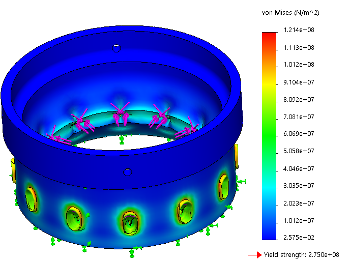
Using Solidworks FEA, I decided that this cross-section worked under the following conditions:
4,330 lb from the forward closure
3 ft-lb preload on the bolts (this puts 960 lb tension in the bolt)
FRR made of 6061 T6 Aluminum

In this design, the wall thickness is only large where the bolt tension is acting, saving quite a lot of mass. This also gives the bolts lots of thread length to engage with.
The FEA was set up with the face that contacts the forward closure fixed. The 4330 lb force is acting upward on the top surface of the bolt holes and 960 lb shear force acts radial outward on each hole to simulate the bolt tension. The safety factor is 2.27.
For the forward part of the FRR, which is designed to interface with the airframe, the design was much simpler. This is because the weight of the airframe rests on the fincan (which rests on the nozzle). The main job of the forward-most screws are to restrict rotation about the central axis of the rocket. There are no major forces that apply this kind of torque on the airframe. These screws also hold the airframe on during the descent back to the ground, but there are no major forces associated with this, either. 4 8-32 screws were used for this.
Manufacturing
TBD - waiting to return to campus
The plan is to use one of the semi-CNC lathes in The Deep as well as a radial indexer.
Testing
Static Fire?