Return to Learning Curriculum
LS6: Injector Design
Lecture Zoom Recording
Original Authors: John Posada '24, jposada@mit.edu & Max Kwon '22, mawkwon@mit.edu
- Note: This LSET is pretty long so check the summary at the bottom of this page if you'd prefer an abridged version
- Great links (for the giga-nerds)
General resources
More advanced resources -- skip for now
4.5 Injector Design
2.1 Injector Flow-System Geometry
But particularly 2.1.1.1 Total Element Pattern
We use a pintle injector on the upcoming Romulus engine if you’d like to learn more!
Huzel & Huang the bread and butter of liquid prop
Rocket propulsion elements textbook
What is an Injector?
The injector is a critical part of a liquid rocket engine (abbr. LRE) that is located between the upstream feed system and the combustion chamber. It is designed to inject the propellants (fuel/ox) from the feed system into the combustion chamber in a way that ensures three main things for the engine:
It optimizes the flow and the impingement of the propellants for optimal combustion
Optimal flow → better fuel efficiency (less uncombusted propellant)
Optimal combustion → better engine performance (more thrust)
It ensures that the combustion is stable for the entire time the engine is fired
It helps preserve the structural integrity of the combustion chamber and the engine itself
Mostly by ensuring that the resulting combustion temperature does not melt the chamber walls
Piping the propellants directly into the combustion chamber without a proper injector would be disastrous for the engine’s mission because none of these points above would be satisfied.
You can think of the injector as the interface between the feed system, which supplies the propellants at certain mass flow rates, pressures, etc; and the combustion chamber, which requires certain performance metrics, pressures, temperatures, etc.
Below is a diagram of the design for the Helios injection system:
This design, unlike the doublet impinging jet design (discussed later), is relatively simple: it simply angles the fuel and oxidizer streams towards each other and slams them together really fast. Below is an image of the actual Helios injector (from a top-down view, as if you are the feed system):

The inner circle and outer ring groove are known as manifolds (discussed later), and the two sets of orifices for the propellants are seen in either of these manifolds. The outermost ring of large holes is just the bolt holes for securing the injector onto the engine.
The magic in the design is the precise hole diameters, angles, and lengths that ensure optimal flow behavior during firing. In addition, more considerations, like which propellant to inject through the centermost manifold, the shape of the manifold, and the number of orifices are very important in the design of this kind of injector. This video shows a cold flow test (water-only) of another style of an impinging jet design.
For those familiar with liquid engines in other types of vehicles, you’ll know that many mix the propellants before combusting them in order to optimize the combustion. In many general aviation aircraft engines and older car engines, you’ll find this premixer is the carburetor. In contrast, premixing in liquid rocket engines is usually not advisable because of the volatility of the propellants, and so ensuring optimal mixing inside the combustion chamber is also a task for the injector. However, do note that in some advanced rocket engines (like SpaceX’s Raptor!), premixing before entering the combustion chamber is a thing that can be done.
Injector Performance
Before we get into the more specific aspects of injector design, it would be good to first understand what principles and metrics we’re trying to satisfy with the injector. Also, throughout the design process, you’ll often want to assess how ‘good’ your injector actually is at doing its job. But how do we evaluate this?
There are a few general metrics and areas that we should always take into consideration to try and evaluate both whether our design does relatively well and whether the design will work within the rest of our engine’s physical constraints. Of course, there will typically be even more metrics used in the research literature for different injector designs, which should also be considered but are not covered here.
Mixing & Atomization
We’re going to mention these words a lot in this LSET. Mixing refers to the actual mixing of the different propellants into a local solution. The better 2 propellants mix, the better they can chemically react when they combust. Atomization refers to the breakup of a flowing propellant stream into individual droplets. This is important because smaller droplets both promote mixing (by allowing space for the other propellant to mix), and vaporization (since it’s energetically easier for a droplet to convert to vapor than an entire stream of fluid).
Droplet Size
This is the ‘measurable version’ of atomization, and a metric we try to minimize. In practice, this is a very difficult thing to actually measure since you’d have to capture images inside the combustion chamber during injection, and because the droplet sizes differ over time, between propellants, and within a single propellant. For the metric, what we do is use one of a number of measurements that tries to capture the ‘average droplet size’. A popular choice among them is the Sauter mean diameter (search it up if you’re curious but don’t think too hard about it).
But how would we find it, anyway? In some cases, we can estimate the droplet size using published empirical formulas (based on the chosen injector design/flow characteristics). We can also use computational fluid dynamics methods (abbr. CFD) to computationally model the flow and estimate it that way. CFD is a little difficult to learn and use properly, though, but it is a very popular tool for verifying flow characteristics.
Impingement Distance
The impingement distance can be defined as the axial distance the propellant travels before impinging with the other propellant. This is an important metric because it tells you at about what point in the combustion chamber you can expect most mixing to begin, and subsequently, a general idea of after where combustion will happen, which is good to know for thermal analysis and making sure your injector doesn’t melt. |
There’s no real desire to have it very close to the injector (which can unnecessarily heat the faceplate) or to have it very far from the injector (which means your combustion chamber will have to be even longer). There are some rules of thumb found in the literature for what impingement distance you should aim for based on your injector type, and they are usually measured relative to the diameter of the orifices in the injector.
Vaporization Length
For the most part, the actual combustion inside an LRE occurs in the gas phase, which is why we want our liquid propellants to mix well before they vaporize so that they can combust more efficiently. The term vaporization simply refers to this conversion from liquid to gas in the propellants as they heat up inside the combustion chamber.
Vaporization length is a rough estimate of how far it’ll take either propellant to travel within the chamber before they vaporize (and thus do the bulk of their combustion). Like droplet sizes, the most that can typically be done is to use a published empirical formula to try and find the vaporization length, then verify this using CFD.
Combustion Stability
This is quite a deep and pretty complex subject that has so much to cover, so we only give a general gist of it here. While the rocket engine is being fired, there are always unavoidable and pretty random chamber pressure fluctuations. If your entire system is designed well, these fluctuations appear just like low magnitude random noise and don't cause a problem. Typically, up to a 5% fluctuation in chamber pressure is permissible (peak to peak pressure), but there are some cases where this threshold must be reduced further.
However, if these pressure fluctuations exhibit a different kind of behavior, it can be disastrous for your system. One common occurrence in unstable combustion is resonance (a phenomenon you might remember from high school physics), whereby these small pressure fluctuations build up additively over time to really destroy your system.
We bring this up because the injector is one of the most influential parts of a rocket engine when it comes to the stability of combustion. We won’t cover here specifically how, but know that the design, and particularly the orifice pattern, of the injector plays an important role in stability, but can come at the price of having to compromise combustion performance and efficiency. In addition, there are some physical structures that can be added to the injector that can help mitigate combustion instabilities (namely baffles and acoustic cavities), but we won’t cover those here.
Common Injector Types
Of course, there is not a single injector design that is best for any liquid rocket engine. Choosing which injection scheme to use depends on the objectives of the mission, experience of the design team, machining limitations, and other factors that must all be considered by the team before beginning development.
Here we cover 3 common types of designs used in liquid rocket engines, but there are many other types and variations to these that can be developed depending on what is needed for the engine.
Non-impinging Shower Head
Just kidding – before we get into designs that are used today, here’s a design that is actually no longer used at all (because history is cool). It simply injects the propellants axially straight into the combustion chamber.

This design was used in the German V-2 rocket and relies on turbulence and the propellants diffusing in order to achieve proper mixing and combustion. It is the simplest non-impinging design but is no longer used because it requires a very large combustion chamber volume to work properly, and other designs are simply better. The following designs are currently widely used in liquid rocket engines.
Impinging Jet
Perhaps the simplest of these, the impinging jet design is simply sets of angled orifices that slam the two propellants together really fast (known as impinging them).
For these, there are considerations like hole diameters, angles, lengths, number of holes, spacing of holes, etc. It is very important to know the point and angles of impingement so that you can make sure you’re not combusting directly onto the chamber wall and melting it.
The primary advantage of this design is its simplicity, which speeds up the design process considerably, and allows the team to machine the injector relatively quickly.
Like/Unlike Impinging Jet
For this design, you can choose to either impinge two like propellants (fuel on fuel, oxidizer on oxidizer) or two unlike propellants (fuel on oxidizer).
Like impinging jets (also known as self-impinging) allow the separate propellants to atomize very well and break up into very small droplets, and result in fan streams that then mix the two propellants for combustion.

Doublets/Triplets/etc.
It may also be beneficial to increase the number of streams impinging at a single point from 2 to 3 or more.
This design can help when there is a mismatch in the fuel and oxidizer stream momentums, which may result in an unfavorable resultant angle (e.g. that could spray flames towards the chamber wall instead of the nozzle exit). Additionally, increasing the amount/momentum of propellant impinging generally also improves the mixing of the propellants.
Pintle
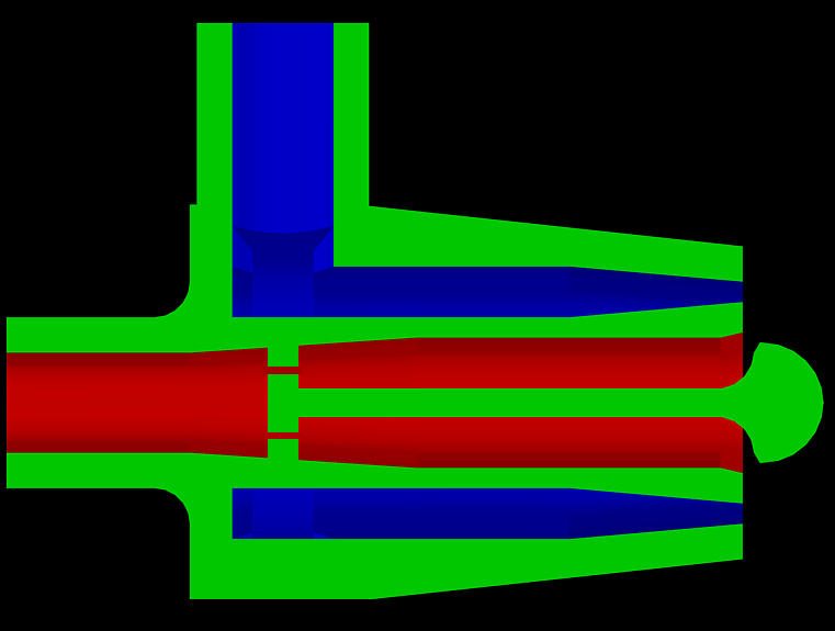
The pintle injector design typically consists of just one element and works by impinging a central radial flow with an outer axial flow as shown below.
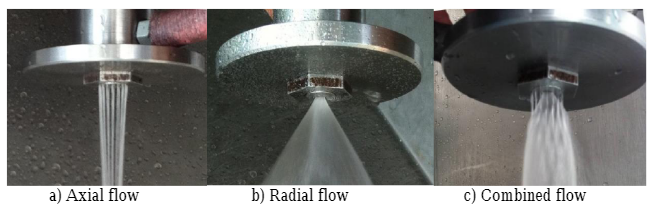
The injector gets its name from the pintle-shaped bit (that green knob thing on the far right of the figure below) that allows the central flow (the red below) to turn from going towards the nozzle exit to spraying radially, more towards the chamber walls. It then impinges directly onto the outer flow (the blue below) which is going axially down the chamber. The result of their combined flow is a cone of liquid film.
→ From feed system | → Nozzle exit |
The pintle injector is a popular injector choice because it’s not incredibly complex, and provides a few notable advantages:
Improved mixing caused by the very sharp angle of impingement, and non-planar impingement area
Lots of freedom in design choices – namely, it’s relatively easy to introduce orifices whose opening area can be changed allows the engine to be throttled (changing how much propellant we are injecting, which allows us to control thrust output)
There has been observed combustion stability inherent to the pintle design
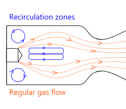
A few theories exist to explain this inherent combustion stability, but it is most likely due to two things: the pintle’s central position in the chamber, and its recirculation zones. These recirculation zones are an important characteristic of pintle injectors and are where uncombusted propellants form (their own respective) loops in the chamber. Here, they deflect the incoming flow, and depending on the thermal profile, can either heat or cool the pintle tip and the chamber walls (it’s kinda complicated!).
The first theory explains that the central pintle is located at a nodal point within the chamber’s acoustic pressure field (you don’t need to know what this means!), and so energy released at the pintle tip doesn’t contribute very much to the pressure fluctuations that cause combustion instabilities. The second theory suggests that the recirculation zones act as a sort of ‘damping zone’ for possible instabilities arising from the combustion gases.
Of course, no design has only advantages. The pintle injector design can be susceptible to undesirable heating both on the pintle tip itself and on the chamber walls. As such, the pintle injector is often complemented by a dedicated cooling system (like regenerative cooling or film cooling!).
Coaxial Swirl
The coaxial swirl injector, as the name suggests, uses two coaxial tubes (called swirlers) that swirl their propellants. Once either propellant exits its swirler, it sprays into a cone of liquid film. Depending on the desired behavior, the cones can be made to collide with each other before reaching the chamber wall or not. Check out this video to see a cold flow test of a coaxial swirl injector.
The primary advantages of a coaxial swirl design are:
Relatively stable across a large range of mass flow rates, allowing for higher mass flow rates than other designs
Don’t worry if that doesn’t make much sense!
This is because the mixing and atomization processes that occur in the chamber are less sensitive to any pressure fluctuations or flow velocity variations with this design since pressure oscillations within the swirling flow itself help stabilize external oscillations
Better atomization of propellants in the cone sheets leads to smaller droplet sizes which also allows for better mixing
Also, the swirling gives the propellants radial, in addition to axial, momentum, meaning they have more time to mix when they enter the chamber
Reduced worry of combustion instabilities
On the other hand, this design is not good for very viscous propellants because of the behavior of the swirlers, which reduces the atomization of these kinds of propellants. In addition, modeling the flow behavior inside the swirlers can become quite complex, especially in the inner swirler because of the presence of a central gas core that forms as the propellants swirl around.
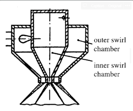
Inner/External Mixing A lot of design choices can be made that affect the overall behavior of this type of injector. One of the major choices is choosing whether to design for inner or external mixing. External mixing is when the inner and outer cones are able to exit directly into the combustion chamber and mix that way. Internal mixing is when the outlet for the inner swirler is recessed far back enough such that the inner cone collides with the wall of the outer swirler, pictured to the right. |

This choice primarily affects the flow behavior (internal mixing can be more difficult to model), and the resultant angle, but there isn’t very much research to back up giving a more specific description than this.
One final note: researching the coaxial swirl injector can be very difficult because a lot of the work on this type of injector was done by Soviet rocket engineers, and most of their records are no longer available or were simply never published. For this reason, you’ll find conflicting information and many different names referring to the same thing (e.g. coax swirls are also known as bi-swirl coax, duplex, double simplexes, etc.). On the other hand, it has been used previously by NASA and notably by SpaceX’s Raptor engine, so information might be found through their organizations.
Non-primary Injection
This is a very general class of injection that typically involves just designing holes or slots that serve a different purpose than the primary injector. Typically these are non-impinging holes implemented for cooling purposes within the chamber.
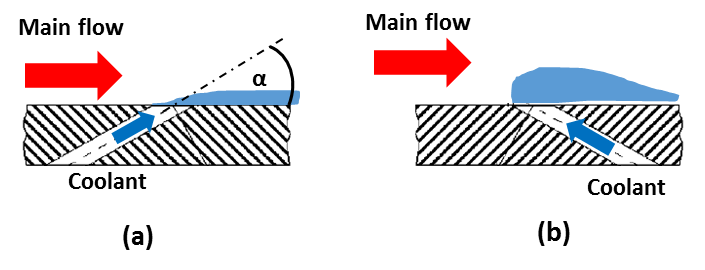
The most common of these is called film cooling. This is when some of the fuel or oxidizer is diverted from the main flow and injected almost parallel onto the walls of the combustion chamber. This forms a protective film of coolant along the chamber wall, which helps keep the chamber wall cool, as illustrated below.
Upstream of the Injector
What occurs upstream of the injector is very important to the design of the injector. Before the propellants enter the injector, several properties must be known in order to properly develop the geometry of the injector.
Feed System Inputs
From the feed system, we must know the mass flow rate of both propellants, the total drop in pressure from their initial reservoir pressure, and the actual properties of either propellant (density, boiling point, etc.). It’s useful to be very familiar with the actual behavior of the fluids, and knowing how, for example, the viscosity may play a role in the injection of the propellants can be critical.
Knowing the feed system inputs allows us to determine the desired aspects of the injector from the desired outputs of the entire engine – remember, think of the injector as the interface between the feed system and the rest of the engine.
Among the most important outputs of the system are the resulting mass flow rates, the pressure drop, and the vaporization length.
A good rule of thumb for initial injector design is that the drop in pressure across an orifice be 20% of the chamber pressure (we discuss more on how to design for this later). This is also referred to as the stiffness of the injector. The relatively large difference in pressure forcefully pushes the propellants through the orifices with high velocity, which is vital to combustion stability. Without that high velocity out of the orifice, the propellants could be subject to flow dribble, where they tend to pool up at the orifice exit, causing poor mixing and hindering the flow into the chamber.
Pressure drop and flow rates also have some effect on combustion stability, but that’s a very difficult topic that we won’t cover very much here.
Manifold
The manifold is a space that properly reroutes the feed system propellant flow into the injector. It can also be thought of as an interface – this time between the feed system and the injector orifices.
Injector Geometry
It’s difficult to give a general overview of the geometry of the injector because it varies from design to design, but there are a couple of key principles that mostly apply to all kinds of injectors. If you begin to work with injectors more closely, you’ll find more detailed design procedures and metrics that you need to account for depending on the design that you choose.
Number of Elements/Orifices
The term element usually refers to the independent set of things that make up a unit of the injector, and varies from design to design. For example, in an impinging jet doublet, a pair of holes is an element, while in a coax swirl, the entire structure is an element.
You can have more than one element, and in some cases, like the impinging jet designs, you will have several of these. Deciding how many elements your injector will have is important because it directly affects the output of the injector (in terms of mass flow, propellant spread, etc.), but also can change other aspects of the geometry of each element.
The main consideration for each element is the size of its orifices. In general, the term orifice refers to a hole, but can also refer to a slot, annulus, or any general ‘exit’ for the propellant into the combustion chamber. Having more elements typically requires each element to have smaller orifices in order to supply the same mass flow, as you will see below.
Sizing
The sizing of orifices in an injector element typically comes from knowing the desired mass flow rate ṁ out of that orifice and the desired pressure drop Δ𝑃 across that orifice. Using the equation below, we can find 𝐴, the area needed for that orifice.
The two other variables, 𝐶d and 𝜌, are the coefficient of discharge and the density of the fluid going through the orifice, respectively.
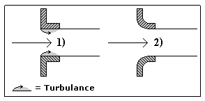
The coefficient of discharge is a nondimensional number that tells us what fraction of mass flow going through an orifice actually ‘gets through’. We can define it as the ratio of actual mass flow to theoretical mass flow out the end of an orifice, and so is between 0 and 1. We usually take an empirical estimate of this number based on the shape of the orifice (e.g. sharp corners experience more flow loss than round corners, so have a lower 𝐶d, illustrated below).
This equation can also be used in reverse, taking a given area (or diameter of hole) and finding the resulting mass flow through that orifice. This can be very useful if there are hard-set manufacturing limits, and is also useful for designing non-primary injections.
In general, a larger number of smaller holes will result in more spread of your propellant and allow for better mixing and atomization throughout the combustion chamber.
Knowing this, you might wonder why we don’t just use a very large number of very small holes to achieve the best performance. In fact, if all we cared about was engine performance, we would! The reason we don’t is that we also have to make the engine ourselves, and choosing to design such precise and difficult-to-machine parts is incredibly tedious and, in some cases, impossible.
As such, always be mindful of the actual manufacturing of the injector when sizing it. Oftentimes, the part will be machined by hand, and you don’t want to be the reason someone is stuck drilling 70 very precise 0.5 mm holes the night before their midterm (and you certainly don’t want to be that person yourself!).
And another note, having a relatively large number of orifices can bring up even more concerns regarding combustion stability, due to more fine patterns causing more unstable energy/pressure fluctuations, but that’s not a topic we’ll delve into very deeply.
Angles
There are 2 important angles to keep track of in the design of the injector: the angle at which the propellant enters the combustion chamber, and the resultant angle of the fluids after impingement. Knowing the entry angle can typically get you a very good idea of the resultant angle if you also know the momentums of the two streams.
Knowing the resultant angle is critical because you want the fluids to combust axially downwards, towards the nozzle exit, and not towards the chamber walls. In some cases, it is sufficient to use this equation, derived from basic collision kinematics (from high school physics!), to find the resultant angle,

Where ṁ is the mass flow rate, v is the velocity, the subscripts 1 and 2 refer to either propellant, and the angles are illustrated below.
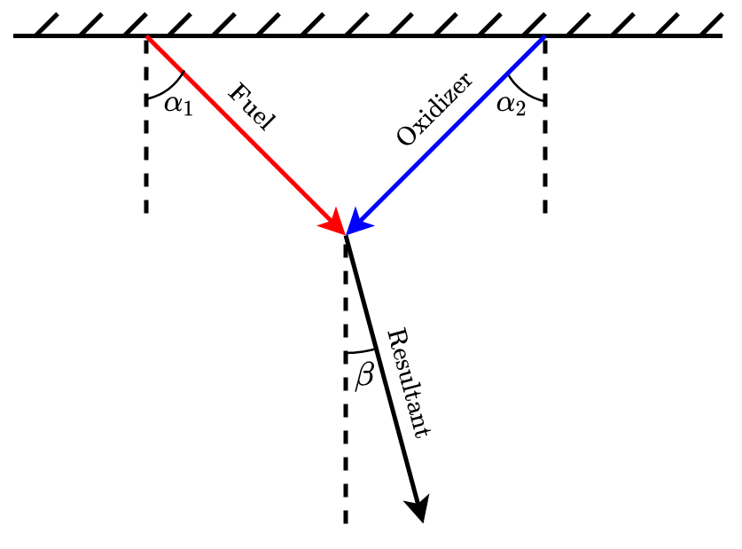
In general, you want the resultant angle to be very close to zero (i.e. going straight down the chamber towards the nozzle exit). Note that we have to use ṁv, the fluid’s momentum per second (units Newtons) because the flow is a moving continuous mass.
Sometimes, though, this approximation does not match empirical data, like with pintle injectors (among other designs or variations). In these cases, there are often published empirical formulas that can be used to acquire a better approximation of the resultant angle.
Orifice Length
The actual length of the orifice, from entry to exit, is actually an important factor in determining the behavior of the fluid flow across the injector. What we want is an orifice long enough to avoid flow separation, a phenomenon we won’t really discuss but just know that it can amplify flow losses – when the flow loses energy (and thus is slower, and can sometimes cause even more problems at the orifice exit or within the stream flow into the chamber). In addition, ensuring the orifice is an adequate size helps us also better avoid the problem of flow dribble that we mentioned earlier.
Most literature agrees that a good rule of thumb (at least for simple impinging jet orifices) is that the ratio of the orifice length to the orifice diameter (its L/d) should be at least 5. Having slightly less than this is sometimes ok, but it’s best to aim for at least that, and not have an incredibly long orifice.
Summary
If you remember nothing from above, or just don’t wanna read all that, at least remember these points!
The injector is a part of the liquid rocket engine located between the feed system and the combustion chamber
Its job is to inject the propellants (fuel/oxidizer) from the feed system into the combustion chamber in a way that
Optimizes the flow/impingement → optimizes combustion
Ensures combustion stability
Makes sure the chamber walls don’t melt
Check out this video of a cold-flow test of a simple injector
Mixing is the mixing of two different propellants into a local solution
The propellants need to be well-mixed in order to combust effectively
Atomization is the breakup of a single propellant stream into individual droplets
Very commonly used as a metric of ‘average droplet size’ is the Sauter mean diameter
Promotes vaporization, since it requires less energy to turn a single droplet into a vapor than an entire stream of fluid
This can be measured by a metric of ‘average droplet size’, and we want to minimize this, if possible
Vaporization is the conversion of liquid propellant into a vapor
Most of the combustion in a liquid rocket engine occurs in the gas phase
It’s critical that vaporization finishes before the propellants reach the end of the combustion chamber, and is measured using vaporization length
The 3 common types of injectors we looked at were:
- Impinging jet: simply injects the propellants through angled orifices so they slam into each other really fast
Very simple to design, but combustion can be unstable Like impinging (fuel on fuel, ox on ox) is good for atomization Unlike impinging (fuel on ox) is good for mixing Unlike doublets are used in our Helios engine! |
Pintle: injects one propellant straight down the chamber, and the other radially
Relatively simple, better mixing Characteristic recirculation zones where uncombusted propellant loops back around in the chamber
Used in our Romulus engine! |
Coaxial swirl: swirls the two propellants in coaxial swirl chambers down towards the chamber, and injects the resulting cones of liquid film
Some stability, better atomization Pretty complex to model and research |
A good rule of thumb is to design the injector to have a pressure drop about equal to 20% of the chamber pressure
Using this formula
Where Cd is the discharge coefficient, a nondimensional number that measures ‘how much flow gets through an orifice’ and can be estimated by the shape of the orifice
In general, a larger number of smaller holes gives better mixing, atomization, and combustion efficiency
But we don’t use this philosophy much because someone is gonna have to machine those tiny holes, and you’ll wish it isn’t you
There may also be worry of combustion instabilities as the number of orifices increases
Knowing the entry angle of propellants into the chamber can give you a good estimate of the resultant angle after impingement
This is critical because we want the fluids going axially down the chamber towards the nozzle exit, not combusting onto the chamber walls
But some designs require more sophisticated empirical approximations
The manifold is the space right before the orifices that makes sure the propellants are distributed evenly across the injector
The shape and volume of the manifolds are designed for desirable flow behavior
Usually (but not always), we prefer to ox-center, meaning the (usually lower temperature) oxidizer is the central propellant – so uncombusted oxidizer will land on the chamber wall and act as a coolant
Rocket combustion always results in random chamber pressure fluctuations
When these fluctuations get out of control, it’s called combustion instability, and it’s very very bad
The injector can be designed to help mitigate these instabilities
Return to Learning Curriculum