Return to Learning Curriculum
LS7: Engine Structural Design
Original Author: Garrett Robinson '24, garrettr@mit.edu
- Great Links
Stress, Strain, and Young’s Modulus
Key Terms
Stress (𝝈): The force per unit area on a material, measured in Pascals
Strain (𝟄): The ratio between the change in length of an object, to its original length
Young’s modulus (E): The young’s modulus is the ratio of stress to strain. This corresponds to the slope of the stress-strain curve, as well as the “stiffness” of the material.
Below is a stress-strain curve for low carbon steel. Look at it for the features described above. Note that every material has a different stress-strain curve and that we can draw this curve experimentally using laboratory equipment (course 2's will do this).
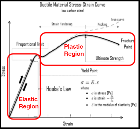
In this image, you can see the different regions associated with a material’s stress-strain curve. The Elastic Region is the region where a material will return to its original shape/length after the stress is released. The Plastic Region is the region where stress is so great that the deformations caused by it are permanent, even after the stress is released. The Yield Point/Yield Stress is the boundary between these two regions. It is the maximum stress that a material can withstand and still return to its original shape/length.
Ultimate Strength (Ultimate Tensile Strength) is another important point on this graph. This is the maximum stress that a material can handle before breaking. A brittle material (chocolate) that cannot be stretched much will have a much lower ultimate strength than a ductile material (copper) that can be stretched a lot.
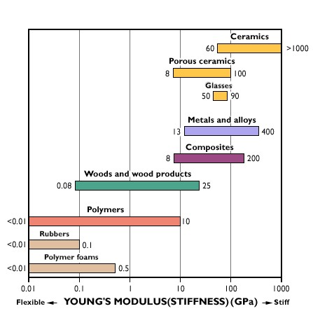
The Young’s Modulus is an important criterion for picking materials. Review the graph below that shows the characteristics of different materials. Note that polymers span the largest range (in terms of order of magnitude), due to how many options engineers have to rearrange their monomer composition.
Hoop Stress
Sometimes when we are designing tanks, engines, cooling channels, and other round geometry in a pressurized system, we need to know that it will be able to withstand the pressure. See this figure below for how to calculate Hoop stress based on pressure, wall thickness, radius, and mean diameter.

When calculating hoop stress, there is an assumption known as the Thin Wall Assumption. This assumes that the wall for the pressure vessel in the calculation has a thin enough wall that the hoop stress is the same for both the inside and the outside of the wall. For the thin-walled assumption to be valid, the vessel must have a wall thickness of no more than about one-tenth (often cited as Diameter / t > 20) of its radius. As this is not always the case, sometimes the mean diameter (as shown above) is used to approximate hoop stress (see “thin wall assumption” Cylinder stress - Wikipedia). The hoop stress only evaluates the radial component of stress; this is almost always greater than the “longitudinal” component, but we should still calculate both just to make sure.
Longitudinal Stress

Longitudinal stress is caused by internal pressure forcing the ends of a closed pressure vessel apart. In a cylindrical pressure vessel, this stress is lesser compared to hoop stress, which can be seen in the equations for stress. Within a pressure vessel, pressure, diameter, and wall thickness will all be equal. The only difference is the constant 2 in the denominator for hoop stress and 4 for longitudinal stress.
Thermal Stress
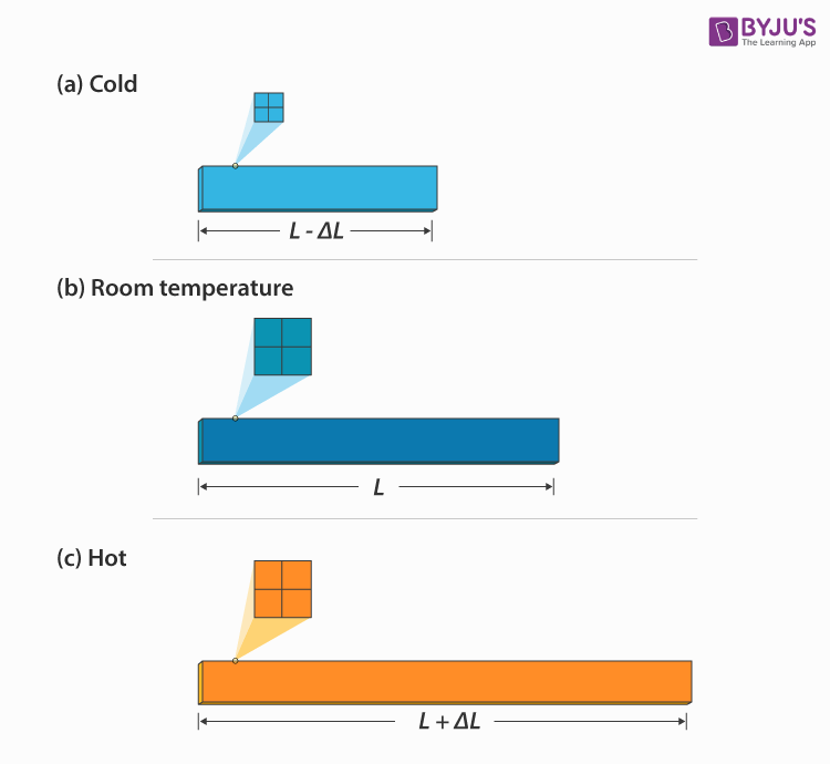
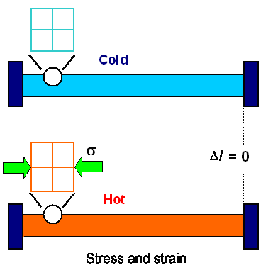
As you may or may not know, materials expand when heated and contract when cooled. Thermal stresses arise when this natural expansion or contraction is prevented or resisted. The image on the right shows this by zooming in on a specific area on a beam that is held in place by walls on both sides. When the beam is cold, there are no stresses on the material, but as it is heated the particles want to expand outward but are held in place by the walls on each side. This creates force inward on the particles in the beam, which is thermal stress.
Simplified Thermal Stress Equation:
E: Young’s Modulus 𝛼: Thermal Expansion Coefficient ΔT: change in temperature |
One final note: researching the coaxial swirl injector can be very difficult because a lot of the work on this type of injector was done by Soviet rocket engineers, and most of their records are no longer available or were simply never published. For this reason, you’ll find conflicting information and many different names referring to the same thing (e.g. coax swirls are also known as bi-swirl coax, duplex, double simplexes, etc.). On the other hand, it has been used previously by NASA and notably by SpaceX’s Raptor engine, so information might be found through their organizations.
Aerospace Materials
There are numerous materials used in the aerospace industry, all for various reasons. Common materials include stainless steel, aluminum, copper alloys, nickel alloys, titanium, and more. These all have unique properties that we will go over that make them useful for specific purposes.
Important Material Properties
Young’s Modulus: Ratio of stress and the resulting strain on a material.
Thermal Conductivity: How well/poorly a material transfers heat. For our purposes, the material that makes up the combustion chamber walls should conduct heat well so that the heat can be transferred quickly to the coolant fluid. This prevents the walls from melting or from weakening enough from the heat of combustion to cause an explosion.
Thermal expansion coefficient: This coefficient represents the rate at which a material will expand/contract when changing its temperature.
Yield Tensile Strength: Stress limits for a material in the elastic region. Any stress beyond this limit will cause permanent deformation of a material.
Ultimate Tensile Strength: Stress limit of a material before it breaks/fractures.
Melting Point: The temperature that a material changes from solid to liquid. This is critical for materials exposed to high temperatures, such as the combustion chamber walls.
Oxygen/oxidizer compatibility: Some materials are more compatible with LOX, H2O2, and other oxidizers than others; for instance, mild steel is not LOX compatible, and brass is not H2O2 compatible. Look up all materials in a chemical compatibility table before using.
Machinability: Some materials need special cutting tools and procedures that can make machining prohibitive. For instance, Inconel is difficult to machine, and titanium is very difficult to weld. Before using an uncommon material, look up its properties. Likewise, it can be useful to machine prototype parts out of an easy-to-machine material, such as Delrin or aluminum to test specifications.
Galvanic Effects: Some materials have electromagnetic interactions in the presence of rain, salt water, and/or oxidizers that cause corrosion when they are in contact. For instance, mixing stainless steel and aluminum can cause galvanic corrosion, and should be avoided for outdoor applications.
Below is an example of the material trade study that we did when choosing between various materials to use for our engine. We ended up choosing Nickel Inconel (not from Markforged though because we chose a different manufacturer) for its high melting point and large tensile strength which outweigh its very low thermal conductivity.
| Material | Melting Point (K) | Tensile Strength (MPa) | Thermal Conductivity (W/m *K) | 1' x 1' x 0.125" Sheet Cost | Manufacturability & Machinability |
|---|---|---|---|---|---|
| Nickel Inconel 625 Markforged | 1563-1623 | 750 at room temp, 560 at 900K | 9.8 at 100℃, ~20 at 700℃ | $325 from Markforged, units unclear | - 3D printing w/ Markforged - low machinability |
| Stainless Steel 305 | 1673-1728 | 193 | 16.2 at 100℃ | About $1.30 | 43% |
| Copper Markforged | 1356.2-1356.6 | ~200 at room temp, ~50 at 800K | ~350 average | $300 from Markforged, units unclear | 20% - Can be 3D printed at Markforged |
| Al 6061-T6 | 855-924.7 | 68.9 | 167 | About $20 | 50% |
| Al 7075-T6 | 750-908 | 71.7 | 130 | About $40 | 70% |
A trade study like this is just designed to let us compare the characteristics of different materials and allow us to weigh our options to make the best-informed decision. As mentioned above, some characteristics might weigh less in our decision -- for example, we care more about the melting point and tensile strength than the thermal conductivity.
Pressure Vessel Design
In Liquid Prop, our full setup to fire a regen-cooled engine has several pressure vessels.
Liquid Oxygen (LOX) Tank
Kerosene Tank
All pipes and valves in the feed system
Combustion Chamber in engine
All of the stresses and many of the material properties that you learned about earlier in the LSET go into designing/choosing pressure vessels for our project.
Tanks
The tank holding LOX must be able to handle the extreme cold from the LOX while also not reacting (oxidizing or corroding) with the LOX.
Feed System
Pipes that hold and move LOX also must be able to handle the extreme cold from the LOX while also not reacting (oxidizing or corroding) with the LOX. They also cannot contract too much due to the cold, as this could prevent the engine from working.
Combustion Chamber
The combustion chamber material must have a yield strength high enough to withstand combustion. It also should be resistant to oxidation and corrosion from the LOX. The walls need to transfer heat to the coolant fast enough to prevent structural weakening, melting, and or an explosion.
Bolted Joint Design
In holding components together at high pressures with high forces, such as in an engine, it is important to evaluate whether bolts and fasteners are able to withstand the forces involved. To do this, we can use a standardized spreadsheet (linked), courtesy of Matt M. Design Spreadsheet - Google Sheets
Specifically for our setup, the engine(left image) is attached to the injector plate through a flange (cross-section is the right image). When designing this joint, placement, tightening, thread engagement, and bolt material were all considered to make sure that they could keep the engine and injector plate together despite intense tensile, shear, and thermal stress.


Torque
Torque is a force that causes an object to rotate. More specifically, torque is the component of a force that is perpendicular to the radial direction from a point of rotation.
The actual equation for torque is:
In our case, torque is used to tighten bolts around the flange to create preload, which prevents the separation of the engine and injector pieces. Keeping these pieces together also prevents fuel leakage from the coolant channels into the outside environment and or combustion chamber through the help of O-rings.
Preload
Preload (also called clamping force) is caused by the initial tightening of a bolt onto a surface. It is the “backup” force on the surface, that is, the amount that you have to push on that joint until it starts to separate. You want to torque the bolt enough so that the joint has a good amount of preload and separation margins, while also not over-torquing the bolt to prevent yield failure of the joint (preload goes beyond yield strength of bolt).
In the equation used to calculate preload, there is a variable, K, known as the K-Factor or the “Nut Factor”. When torquing a bolt, most of the torque just becomes friction between the head of the bolt and the surface, or the nut and the surface. Only ~10% is translated into actual tensile clamping force. The K-Factor represents this friction between surfaces.
Tensile Stress
When forces pull apart a bolt, this is called tensile stress (same equation as stress initially mentioned at the start of the LSET). Because of Newton’s Third Law, every action has an equal and opposite reaction, preload from a bolt that clamps down on a surface will also pull the bolt apart creating tensile stress. This is why a bolt cannot be tightened too much, as the bolt can fail if tensile stress becomes greater than its ultimate strength. |
|

Bolt Spacing
When using bolts, the spacing between the bolts must be considered. Bolts cannot be placed too far apart from each other as this can cause the material between the bolts to have a lower clamping force. This can lead to the separation of the flange pieces due to the extreme pressures inside the combustion chamber and coolant channels forcing the pieces apart. The bolts themselves can also fail if they are spaced too far apart since forces and the resultant stresses could become greater than the bolts’ ultimate strength.
The equation to find max bolt spacing is:
Diameter is the nominal diameter of the bolts used, Thickness is the flange/plate thickness
Shear Stress
Bolts holding flanges or plates together can experience opposite forces, perpendicular to their axis. This is known as shear stress.
Shear stress can be calculated with the equation below, but it is also often assumed to be 60% of the ultimate tensile strength of a bolt.
Shear stress is mainly a concern with the threads of a bolt shearing off, which will be discussed in the next section.
Bolt Threading
General Thread Engagement Rule: The minimum length of engaged threading should be equal to the diameter of the bolt. If too few threads are engaged with the clamped material, then we risk the shear stress on the individual threads becoming too high. This can lead to the thread ripping (shearing) off causing bolt failure. |
Return to Learning Curriculum