...
- Aluminum 6061-O was chosen as the material because welding the inner step probably eliminated its the material's temper.
- No connections were set.
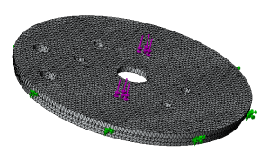
- The outer step was chosen as the fixed geometry. Technically, the Avionics Bay Coupler only constrains the outer step in one direction (the vertical direction), but the bulkhead is also constrained radially within the Avionics Bay Coupler by the inner step. The bulkhead is not strictly constrained circumferentially except by friction after putting the Avionics Bay Coupler under compression (in an ideal execution of the design, which was not necessarily achieved for this test): this is irrelevant to the load applied.
- 1750 pounds were applied to each of the two bolt holes used during the test. Technically, a more accurate representation would be to include the bolts in the model. Using just the bolt holes isn't perfectly accurate because the load was actually applied to the outer side of the bulkhead by the heads of the bolts rather than in the bolt holes (which were not threaded).
- The finest possible mesh was generated. An image is featured below, which also summarizes the previous steps.
...
As the following figure shows (in particular, pay attention to the red arrows indicating yield stress strength vs. stress experienced by the material), the bulkhead saw serious material exceedance.
...