...
- Research was conducted to narrow down a set of materials that provided sufficient thermal insulation while being reasonable to buy and fabricate with. These materials ended up being:
- Nylon 66 3D print - somewhat more heat-resistant than PLA or SLA, though still runs the risk of softening.
- Carbon carbon fiber - very heat-resistant. Pure carbon fiber may soften from heat, depending on the thickness. May be difficult to work with, given the size of the aeroshells and the team's level of experience with composite materials.
- Other composite materials - same as carbon fiber, but the team has limited experience with it.
- Some design ideas were generated:
- Incorporating a mirror so that the camera can be oriented differently from the direction we want a recording of.
- In-flight vibrations were found to not interfere with this type of design.
- Incorporating air pockets for increased insulation
- Using aerogel
- It's expensive
- Using honeycomb structures such as Nomex
- Adds a lot of thickness
- Using aerogel
- Relocating the onboard cameras to inside the rocket.
- People really wanted them on the exterior though.
- Using the shape of the existing but unused aeroshell CAD model made by Chad Meier '23.
- Incorporating a mirror so that the camera can be oriented differently from the direction we want a recording of.
...
After the cancellation of Project Medusa, the remaining members of the Medusa Aerodynamics subteam was (Vealy Lai '26, Conrad Casebolt '26, Ethan Wong '26) were absorbed into Project Prometheus and turned its their primary focus to developing the aeroshells. With renewed efforts, a clearer design process was defined for this component.
...
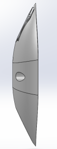
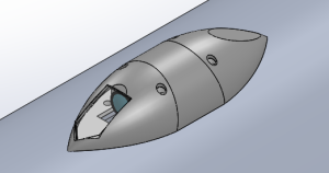
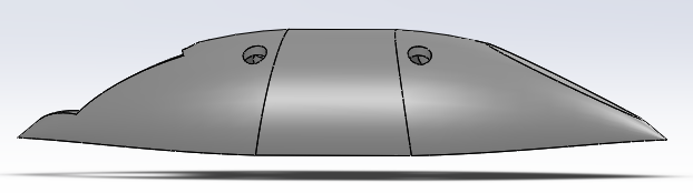
The aeroshell is streamlined on both ends. Its diameter is only minimally larger than the Foxeer Camera which it houses.
(Previous Iteration of Aeroshell IAP 2024)
Aerodynamic Testing
CFD analysis will be performed in the future.
- Update 5/5/24: No aerodynamic or thermal simulations have been conducted on the aeroshells
Manufacturing (Nov. 2023)
The aeroshell mold is 3D printed using PLA. A piece of heat resistant glass is cut to the required shape. Three layers of Carbon Fiber carbon fiber are attached to the exterior of the mold with an epoxy layup using a vacuum bagging technique.
- We performed this procedure for two first-iteration aeroshells, but the carbon fiber did not bind well to the outside of the aeroshell. It is difficult to map the planar sheet of carbon fiber onto the steeply curved exterior of the aeroshell. As a result, a negative mold may be used in the next iteration.
Thermal Testing
In order to recreate the thermal loads experienced by the aeroshell, the aeroshell will be exposed to the stagnation temperature of 350°F using a heat gun for one minute. It will be mounted to a piece of fiberglass to emulate the exterior of the mission package tube.
- Thermal testing concluded that fiber glass is a better choice of composite for the Aeroshell compared to carbon fiber. An identical fiber glass aeroshell maintained a lower internal temperature compared to a carbon fiber counterpart.
Current Design (April 2024)
Overview
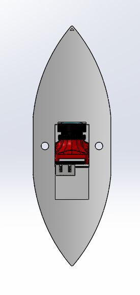
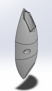
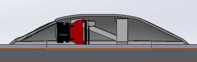
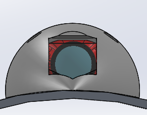
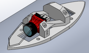
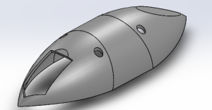
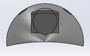
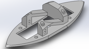
The current design features two separate parts: The Shell and the Skeleton. There is also a glass panel attached to the end of the viewing aperture and camera.
Shell
Skeleton
Manufacturing
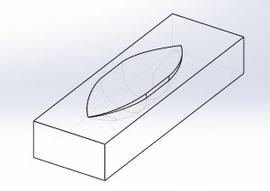
Due to the non-planar shape of the shell, the only viable method of manufacturing is to use a negative mold with composite-epoxy layups sealed in a vacuum bag. The general overview of the process is as follows:
- Print a negative mold of the shell using PLA.
- Perform three consecutive epoxy layups in the negative mold using three layers of fiber glass composite, abiding by the general procedures of epoxy layups.
- Vacuum bag the negative mold and hold near/complete vacuum for 24 hours using a vacuum pump.
More detailed instructions can be found here.
Results
These Aeroshells flew on the Prometheus test flight in April 2024. All four remained intact through subsonic flight speeds and an estimated apogee of 5,000 feet (**double check this CC 5/16/2024). Only one Aeroshell carried a live camera, and the footage captured was deemed sufficient documentation of the booster recovery system deployment. The camera did not overheat during flight or on the pad.
Integration
The two-piece approach necessitates the following integration steps:
- Mount the skeleton to the mission package tube using four (4) M3 or 1/8" screws and corresponding nuts, with the nuts inside **or outside? CC 5/16/2024** the MPT.
- Attach the camera to the skeleton and connect the camera to the avionics bay.
- Mount the shell to the skeleton using four (4) M2 screws.
Future Design Improvement Ideas (as of May 2024)
- The exterior screws should be angled to keep the screw heads normal to the face of the exterior shell.
- The exterior screws are currently threaded directly into the PLA of the skeleton. A future design should add a threaded metal component on the skeleton in order to better secure the assembly together.
- The aerodynamics of the up- and down-facing aeroshells are similar but not identical. Perhaps a new glass shape could be designed, or non-planar glass could be used.
- The cross-sectional profile could be further reduced by using a parabolic shape instead of circular, although a redesigned shell must retain adequate room for the structural supports of the skeleton.
- The field of view could be increased.