...
In the assembly, there is one face seal, which interfaces with the combustion chamber. We were a bit concerned that there would be plastic deformation here when torquing the bolts, as we sized the injector such that the face with the face seal on it contacts the chamber before the injector flange contacts the chamber flange. However, we were able to validate that the lip with the face seal on it would not snap or plastically deform with +/- 0.002" tolerances.
Centerbody
Pintle Tip
i. The Pintle Tip
Purpose: Injection of N2O oxidizer into Osiris combustion chamber

ii. Nitrous Oxide Flow Regimes
Nitrous flow can exist in either the SPI or HEM regime, where SPI stands for Single-Phase Incompressible and assumes quality of zero, meaning the nitrous remains 100% liquid. HEM stands for Homogenous Equilibrium Model and accounts for flash vaporization at the orifices. Flow regime impacts the mass flow rate equation which can be described as
| LaTeX Math Block | ||||
|---|---|---|---|---|
| ||||
\dot{m}=C_d A \sqrt{2 \rho_1 \Delta P} |
and
| LaTeX Math Block | ||||
|---|---|---|---|---|
| ||||
\dot{m}=C_d A \rho_2 \sqrt{2 (h_1-h_2)} |
for SPI and HEM respectively, and is therefore critical to accurate characterization of orifice coefficient of discharge. As manifold to chamber pressure drop increases, the likelihood of flow existing in HEM regime increases, therefore the first design step was determining flow regime at max throttle.
iii. Dyer Model and Supercharge
Initial estimates were based on the Dyer Model, specifically the parameter k, which is a ratio of vapor bubble growth time to fluid residual time. Large k values imply that flow approaches SPI while small k values imply that flow approaches HEM. Assuming a manifold pressure of 600 psi, chamber pressure of 350 psi, and nitrous density of 876.2099466 kg/m^3 at max throttle,
| LaTeX Math Block | ||||
|---|---|---|---|---|
| ||||
K=(P_{initial}-P_{chamber})/(P_{vapor}-P_{chamber}=1.163 |
P_vapor is calculated with CoolProp by solving for nitrous temperature given manifold pressure and density, then using temperature and a quality of 0 to solve for saturation pressure. This result, combined with a low orifice length/diameter ratio implies that flow will remain SPI. The Dyer Model was chosen primarily because it was designed to account for supercharge, as opposed to purely self pressurized. On Osiris nitrogen is used to supercharge the nitrous.
iv. Cold Flow Test Results
Cold flow testing was performed with the intent of characterizing orifice coefficient of discharge and confirming flow regime, however results were inconclusive. cd was calculated by integrating the SPI mass flow rate equation and assuming a pressure drop from an injector manifold pressure transducer to atmospheric. It should be noted that pressure transducers were reading -4 as atmospheric and results adjusted accordingly.
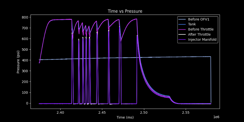
cd values were somewhat scattered. Lower values towards the end are likely a result of nitrogen running through the components tester. Additionally, between peaks 4 and 5 manifold pressure was not given the time to return to the atmosphere. Regardless, no clear trend can be seen between cd value and throttle state. In the HEM regime cd should decrease as a function of dP and in SPI it should remain relatively constant. In both cases an increase in dP correlates with an increase in cd.
v. CFD
Additional CFD was performed using ANSYS Fluent with the goal of analyzing flash vaporization and the orifices and cavitation within the pintle itself. Inlet pressure was set to 600 psi and outlet pressure to 350 psi, with an operating pressure of also 350 psi. The multiphase mixture model was enabled for liquid and vapor nitrous. Results indicated no cavitation.

vi. Design Optimization
From these results, the flow regime was assumed to be SPI and the coefficient of discharge .8. From these assumptions, the ideal orifice area could be calculated and used to determine orifice geometry. An additional orifice was added at the base of the pintle tip to prevent flow instabilities and heat damage. It was sized based on the difference between ideal and actual orifice area.
vii. Water Hammer
Water hammer concerns were raised by BlueShift engineers at the first hot fire attempt, suggesting threads might fail during hot fire. Hand calcs based on modified Hooke’s Law
| LaTeX Math Block | ||||
|---|---|---|---|---|
| ||||
C=\sqrt{\frac{1}{\rho(1/K+D/(Ee))}} |
and Joukowsky
| LaTeX Math Block | ||||
|---|---|---|---|---|
| ||||
P=\rho CU |
P=CU indicate 995 psi max pressure. SolidWorks FEA indicates 2.2 min factor of safety. https://www.fluidmechanics.co.uk/hydraulic-calculations/water-hammer-surge-analysis/
