For Project Osiris, two injectors were designed and manufactured: one for the ablative chamber, and one for the regenerative chamber. Each injector was composed of three parts (baseplate, centerbody, pintle tip) but only the baseplate was different across the two designs.
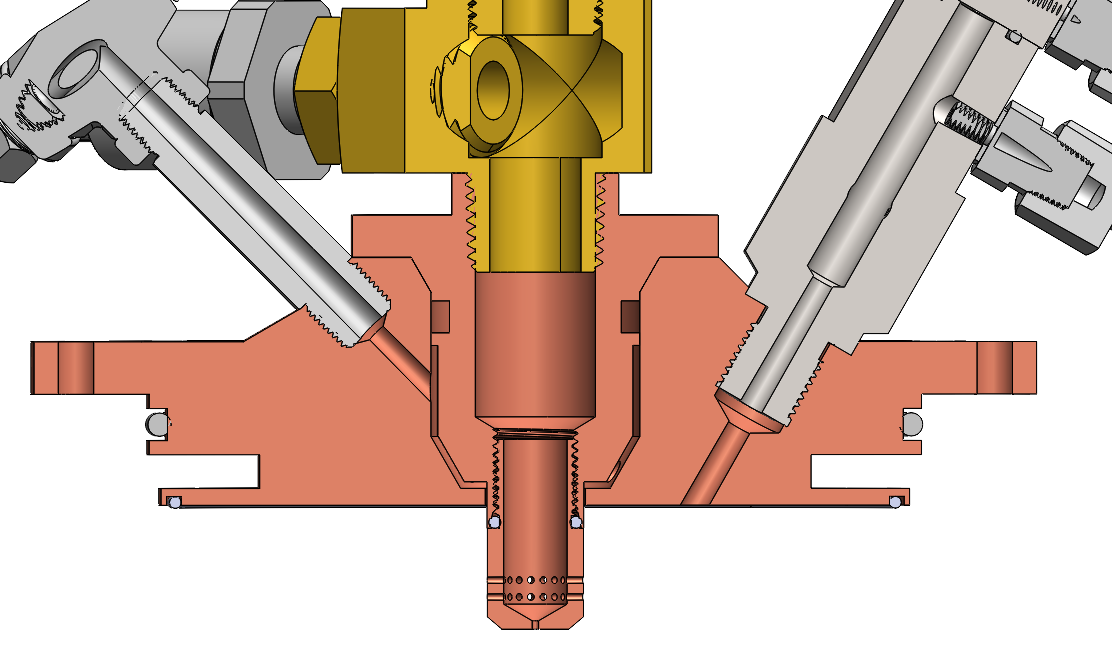
In this cross section showing the regenerative injector assembly, the three components that make up the injector can be seen (baseplate, centerbody, tip). The pintle tip threads into the centerbody via an ORB fitting. The centerbody interfaces with the baseplate via a bolted taper, which we chose to mitigate pintle concentricity issues. However, we still shim the annulus during assembly to make sure the annulus is fine (its width is 0.01").
...
P=CU indicate 995 psi max pressure. SolidWorks FEA indicates 2.2 min factor of safety. https://www.fluidmechanics.co.uk/hydraulic-calculations/water-hammer-surge-analysis/

FOD Issues
Pintle injectors at the amateur scale are oftentimes plagued by FOD due to very small annular gap sizes and tolerances. Even a +/- 0.001 tolerance on a classic pintle annulus can vary mass flow by around 10 percent, which may be unacceptable depending on your requirements. Additionally, a small annular gap means that any contamination in the system can clog it, which would lead to combustion instability.
A good amount of big boy aerospace industry people will claim that collegiate teams are not capable of having a cleaning standard high enough to prevent FOD clogging of an annulus this small (and will thus advise against a pintle or suggest some weird variants of it), but we found that flushing the system with water multiple times (without it hooked up to the injector) has resulted in very clean water flows. At this point, however, we are more concerned about FOD generators (i.e. chattering check valves) but this hasn't caused a real problem for us yet.