For Project Osiris, two injectors were designed and manufactured: one for the ablative chamber, and one for the regenerative chamber. Each injector was composed of three parts (baseplate, centerbody, pintle tip) but only the baseplate was different across the two designs.
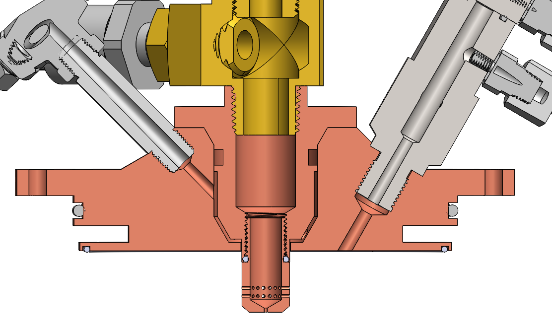
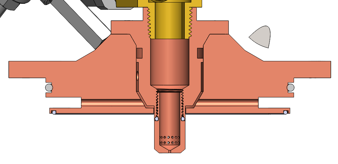

In this these cross section sections showing the regenerative injector assembly, the three components that make up the injector can be seen (baseplate, centerbody, tip). The pintle tip threads into the centerbody via an ORB fitting. The centerbody interfaces with the baseplate via a bolted taper, which we chose to mitigate pintle concentricity issues. However, we still shim the annulus during assembly to eyeball concentricity. Our annular gap is 0.01".
You can also see three ports; the left port is for probing fuel manifold temperature and pressure, and the right is for the igniter (see the ASI section). The fuel sensing port is a 1/8" NPT, and the ASI port is a 1/2-20 ORB. The top axial port routes N2O to the pintle tip. There is also a fourth port that senses chamber pressure. Our main chamber pressure sensing PT connects to the ASI, but we wanted an additional PT to capture main engine startup transients. We'll probably plug this port for our actual flights on the lander.
Fuel comes up from the regen channels and feeds into the injector manifold, and then through the annulus. A small part of the fuel (~15% total fuel mdot) is used as film cooling, and is discharged through the ring of 10 9 0.5mm holes.
Centerbody
The centerbody inlets N2O at around 600 psi with an ORB fitting (it's an NPT in the photo, but we switched to ORB because ORB superiority). Really though, you should try to minimize the number of NPT fittings going into your injector, as you're probably going to run into a lot of integration issues that will make you uninstall and reinstall injector fittings multiple times.
...