Overview
For Project Osiris, two injectors were designed and manufactured: one for the ablative chamber, and one for the regenerative chamber. Each injector was composed of three parts (baseplate, centerbody, pintle tip) but only the baseplate was different across the two designs. Since the goal of the project is the regenerative chamber (see Ablative Chamber for the reason behind the ablative), this page will focus on the regenerative injector variant (see bottom for Ablative info).
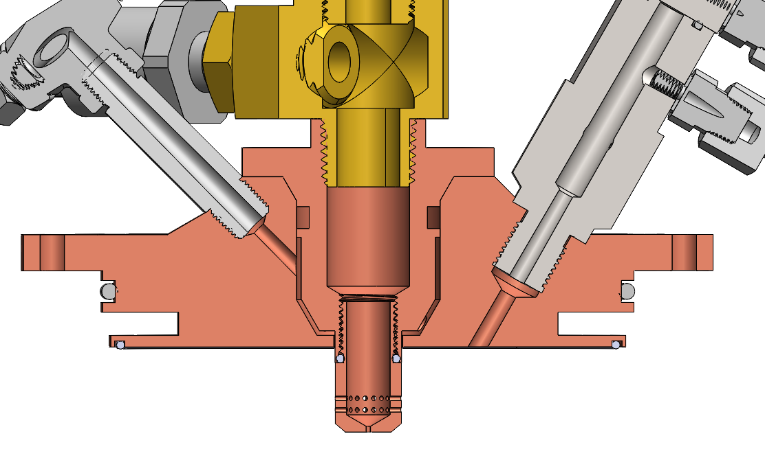
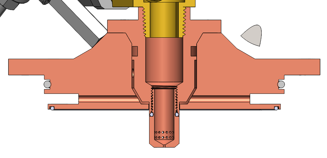

In this these cross section sections showing the regenerative injector assembly, the three components that make up the injector can be seen (baseplate, centerbody, pintle tip). The pintle tip threads into the centerbody via an a 5 (1/2" 20 Thread) ORB fitting. The centerbody interfaces with the baseplate via a bolted taper, which we chose to mitigate pintle concentricity issues. However, we still shim the annulus during assembly to make sure the annulus is fine (its width eyeball concentricity. Our annular gap is 0.01").
You can also see two three ports; the left port is for probing fuel manifold temperature and pressure, and the right is for the igniter (see the ASI section). . The fuel sensing port is a 1/8" NPT, and the ASI port is a 1/2-20 ORB. The top axial port routes N2O to the pintle tip. There is also a fourth port that senses chamber pressure. Our main chamber pressure sensing PT connects to the ASI, but we wanted an additional PT to capture main engine startup transients. We'll probably plug this port for our actual flights on the lander.
Fuel comes up from the regen channels and feeds into the injector manifold, and then through the annulus. A small part of the fuel (~15% total fuel mdot) is used as film cooling, and is discharged through the ring of 10 9 0.5mm holes.
Face Seal
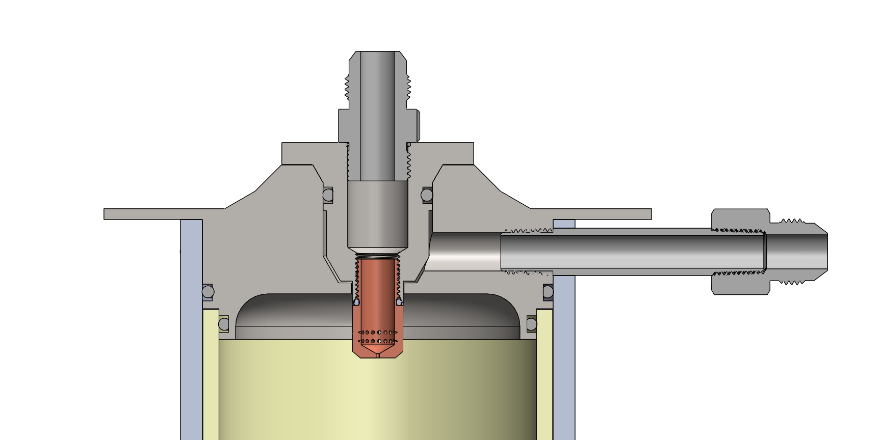
In the assembly, there is one face seal, which interfaces with the combustion chamber. We were a bit concerned that there would be plastic deformation here when torquing the bolts, as we sized the injector such that the face with the face seal on it contacts the chamber before the injector flange contacts the chamber flange. However, we were able to validate that the lip with the face seal on it would not snap or plastically deform with +/- 0.002" tolerances.
Centerbody
Centerbody
The centerbody inlets N2O at around 600 psi with an ORB fitting (it's an NPT in the photo, but we switched to ORB because ORB superiority). Really though, you should try to minimize the number of NPT fittings going into your injector, as you're probably going to run into a lot of integration issues that will make you uninstall and reinstall injector fittings multiple times.
There is a tee fitting upstream of the centerbody that gives us nitrous manifold pressure. It's probably a somewhat rough estimate as the flow has to constrict a lot more before it exits the pintle orifices, but since our control loop controls nitrous mdot indirectly through pc measurement, it doesn't really need to be that accurate.
Pintle Tip
Purpose: Injection of N2O oxidizer into Osiris combustion chamber
...
From these results, the flow regime was assumed to be SPI and the coefficient of discharge 0.8. From these assumptions, the ideal orifice area could be calculated and used to determine orifice geometry. An additional orifice was added at the base of the pintle tip to prevent tip melting; if there is no hole there, the nitrous will stagnate and be trapped underneath the radial orifices, causing it to flash boil, which then lets the hot gas melt the tip. The hole was sized based on the difference between ideal and actual orifice area.
...
A good amount of big boy aerospace industry people will claim that collegiate teams are not capable of having a cleaning standard high enough to prevent FOD clogging of an annulus this small a 10 thou gap annulus (and will thus advise against a pintle or suggest some weird variants of it), but we found that flushing the system with water multiple times (without it hooked up to the injector) has resulted in very clean water flows. At this point, however, we are more concerned about FOD generators (i.e. chattering check valves) but this hasn't caused a real problem for us yet.
Annular Gap Trades
Although I say that small annular gaps are fine, there is, of course, a limit to that. I've seen people do gaps as small as 0.003" successfully, but we tried our absolute hardest to make our gap as large as possible. To do that, we had to trade annular gap with pintle diameter, fuel manifold pressure, throttling, and stiffness. Our requirement is to stay above 15% dP/Pc for both manifolds, which becomes a challenge as you throttle down because the "dP" decreases faster than the "Pc" as you throttle. However, lower stiffness also means a larger annular gap for the same mdot, as your "A" term needs to increase to compensate for a lower "dP" term. As for pintle diameter, we scaled it down as much as we reasonably could. If we had scaled it down to be even smaller than it currently is, we would have gotten a huge pressure drop into the pintle tip, and the radial holes around the tip probably would not have fit. There is a rule of thumb from somewhere that says your chamber inner diameter should be 3-5x your pintle diameter...I'm pretty sure this is bogus. This trade ultimately had us converge on a manifold pressure of 500 psi at full throttle.
Face Seal
In the assembly, there is one face seal, which interfaces with the combustion chamber. We were a bit concerned that there would be plastic deformation here when torquing the bolts, as we sized the injector such that the face with the face seal on it contacts the chamber before the injector flange contacts the chamber flange. However, we were able to validate that the lip with the face seal on it would not snap or plastically deform with +/- 0.002" tolerances.
Ablative Injector
The injector was fully designed and spec'd for the regenerative chamber and then modified to fit the ablative system. The main modifications were to remove the radial holes for fuel passthrough and face seal flange. Instead, fuel enters through a port on the side of the chamber (think only one radial fuel through hole), and there are a pair of face seals (one for ablative liner one for chamber wall) in place of the face seal + radial seal on the regen. Since the ablative chamber is not designed to run at steady-state, this baseplate was machined out of steel to function as a high-temp heat sink. See CAD below:
Note:
For the actual ablative injector the NPT fitting at the top of the centerbody was replaced with an ORB due to that fitting being removed often. The centerbody was also made out of copper since the steel regen centerbody was dropped, and so the copper part intended for the regen injector was used instead (it is the same part dimensions exactly).
Additionally, the ablative chamber flange was too thin (somehow slipped under the radar through both PDR and CDR), and so a thick steel supporting plate was added during engine integration, sitting "on top" of the injector.