B-AV002 Avionics Mount.pdf, B-AV005 Avionics Bulk Head.pdf, B-AV101 (Pyxida Panel).pdf, B-AV201 (Telemega Panel).pdf, B-AV301 (Raven + Dennis Panel).pdf
Part | Component Status | Responsible Engineers |
|---|---|---|
| Booster Avionics Tower B-AV000 | Manufacturing Prep | Laura Schwendeman 2023 Quin Bowers 2023 |
Purpose/ description:
A structure meant to house the avionics equipment for the Phoenix booster.

Requirements:
1.1. Must be able to survive acceleration of the rocket (196 m/s^2)
1.2. Must be able to survive the vibrations of the rockets
1.3. Must fit within mission package tube
1.4. Must hold all required avionics components and allow them to function
1.5. Must be relatively easy to integrate and attach into the rocket
The Booster Avionics Tower is composed of many components that house all of the avionics equipment required for flight. Its design was inspired by Hermes AV Towers, which housed electronics on a set of panels. The Booster Avionics Tower uses 3 panels.
The Booster Avionics Tower is composed of 5 main subcomponents: The antenna mount, the 3 panels, and the Piston Mount.
Estimated Weight (based off of CAD Model)*: 329.78 grams, approx. .727 lbs
Design Brief:
The booster AV Tower is basically a duplicate of its Sustainer counterpart. We attempted to modify it to retain all the components on the sustainer tower, but were unable to make it any shorter despite the increased diameter. In the end, avionics decided they could ditch the 10inch antennae and several of their largest boards. We managed to squeeze the tower around the piston, meaning it adds negligible height to the rocket. (yay!)
CAD Design:


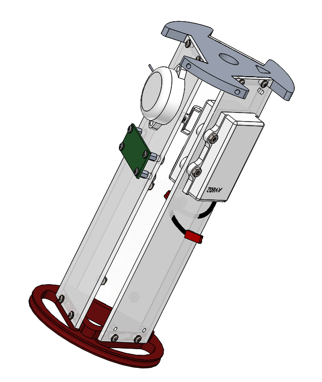
Antenna Mount:

The Antenna Mount serves two purposes. It acts as a cap to attach and constrain the 3 panels with all of the boards, and it also serves as a mount for a ring antenna that communicates with avionics components.
The antenna mount was designed so that the patch antenna would be placed as far apart as possible from the metal in the piston, while also reducing the overall length of the booster. Antennae experience interference from nearby metal objects. This is why the patch antenna was not permitted to overlap with the piston and why it is as far as possible from the metal in the motor casing aft of the Avionics tower.
Manufacturing: 3D print from PLA, using stl from cad model.
B-AV100, B-AV200, and B-AV300 Panels:
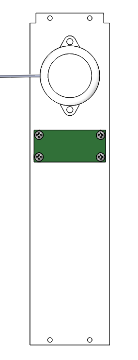
These polycarb panels provide mounting holes for pcbs and other flat components. These are the most important parts of the tower, held together and attached to the rocket by the others.
Manufacturing: Waterjet polycarb
- Position polycarb in Waterjet bay
- Restrain polycarb from the sides using additional metal, secured using clamps and weights
- Ensure water level is below polycarb sheet to prevent it from floating
- Zero Waterjet, begin cutting
- pause the machine and remove panels each time one is cut to prevent them from falling


Piston Mount/Avionics Tower Mount/Avionics Bulkhead:

The Avionics Tower Mount in the booster serves two purposes. It fixes the Booster Avionics Tower to the booster airframe and interfaces with the piston and fixes it to the rocket as well.
FEA analysis for the Avionics Tower mount.
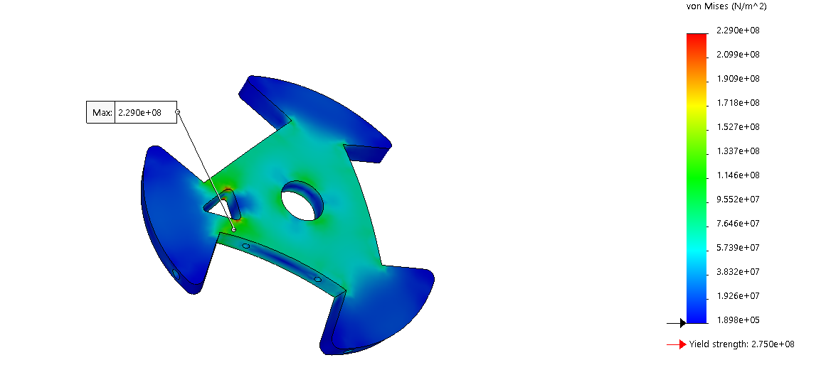
Notes on FEA:
The piston mount must withstand both the accelerated mass of the avionics tower below and the force of the piston when firing.
The FEA from the part currently shows that the max stress does not exceed the yield strength of 6061-T6 aluminum, the proposed material for the part.
The current max stress does not currently give a safety factor of 2, but the max stress currently only occurs at over a small volume of the part. Most of the part experiences a max stress that fall below the Yield strength of the material with a safety factor of 2
Future designs for the part hope to further reduce stress on the material and potentially reduce weight by making mass saving cuts in the outer regions of the part which experience the minimum amount of stress.
Manufacturing: Waterjet profile, use the radial indexer for radial holes and a mill for the panel mounting holes. Finally, tap all screw holes.
Integration:
Summary Tables:
Manufactured Parts
Part Name | Material | Manufacturing Method | Cost |
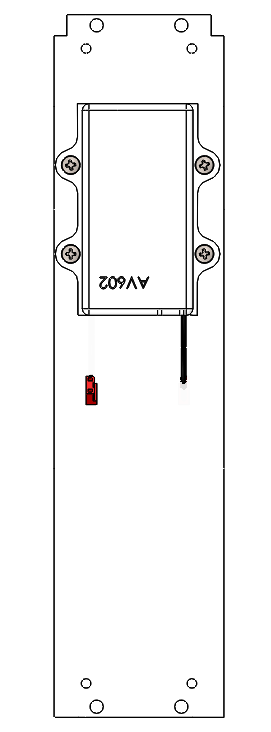
B-AV002 Avionics Mount | ABS/PLA | 3D print | 0 |
B-AV100 Raven Panel | Polycarbonate | Waterjet | |
B-AV200 Telemega Panel | Polycarbonate | Waterjet | |
B-AV300 Battery Panel | Polycarbonate | Waterjet | |
B-AV005 Avionics | 6061-T6 Aluminum | Waterjet + Lathe + Drill | |
B-AV203 GPS Holder | ABS/PLA | 3D print | 0 |
B-AV105 Beeper Holder | ABS/PLA | 3D print | 0 |
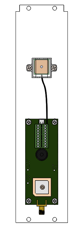
Avionics Components housed on the Booster AV Tower:
Part Name | Quantity | Material | Cost | Link |
AV302 Raven | 1 | --- | ??? | https://www.featherweightaltimeters.com/raven-altimeter.html |
AV105 Adafruit Passive GPS | 1 | |||
Beeper | 1 | http://www.com-spec.com/rcplane/manual/RC-SP_MP_HP_Manual.pdf | ||
TM000 Telemega | 1 |
Fasteners:
Passivated 4-40 .125 Stainless Steel Pan Head Phillips Screw | 16 | Stainless Steel | 4.27 (for 100) | |
3/16” Standoff | 8 | Aluminum | 6.88 | |
4-40 Heat set inserts | 3 | Brass | 9.05 (for 50) | |
Passivated 4-40 .25 Stainless Steel Pan Head Phillips Screw | 12 | Stainless Steel | 3.39 (for 100) | |
4-40 .25 Hex Nut | 16 | Stainless Steel | 3.02 (for 100) |
Part list for Phoenix Avionics Tower:
| Part Name | Location | Dimensions (roughly) | Notes | Link | Quantity |
|---|---|---|---|---|---|
| Pyxida | Pyxida Panel | ||||
| Telemega | Telemega panel | ||||
| Raven | Telemega Panel | ||||
| Dennis | Dennis Panel | ||||
| Power Management Board | Dennis Panel | ||||
| Multicolor LED | On Power Management Board | ||||
| 18650 SMD Batteries + holder | Behind Power Management Board | 3.38583in x0.8149606inx0.708661mm | 3 | ||
| Antenna #1 | On the Disk | 2 | |||
| Antenna #2 | On the Disk | 2 | |||
| 6-32 Screws | Everywhere | 12 | |||
| Heat Set inserts | Everywhere | ||||
| Standoffs | Everywhere |