Return to Learning Curriculum
LS4: Fittings & Seals
For any questions: ahodge@mit.edu or Slack DM
Intro
High pressure engine feed systems have many connections, junctions, and matings that are required to piece together each component. At each connection, it’s important to have a sealing design that will ensure the component’s safety and efficiency at any expected system environments. In this learning set, we will look at the different types of seals and fittings commonly used in pressurized fluid systems, and develop an understanding of how these seals work, and how we can properly choose/design them for each application.
Extra Resources
The best resource I found for learning more about types of fittings and threads is this short (~20min total) video series by Brennan Industries. If you want to be a fittings expert quickly, watch through these videos after you read through the LSET: https://www.youtube.com/watch?v=Vt4fWXF7V0g&list=PLXf0h1_tzcaqKocwvA0pCDqbdL3njexgA
The bible of o-ring design is the Parker O-ring Manual, though I prefer this more modern guide by Apply Rubber, from which I have stolen many illustrations. Both of these will be added to the curriculum materials folder.
Important Terminology
Flared Tubing - Tube flaring is a method of forming the end of a tube into a funnel shape so it can be held by a threaded fitting. | |
Bore - hole drilled or machined out of some material. In our applications, we’ll be dealing with cylindrical bores. | |
Gasket - A mechanical seal which fills the space between two or more mating surfaces to prevent leakage from or into the joined objects while under compression. O-rings are a type of gasket. | |
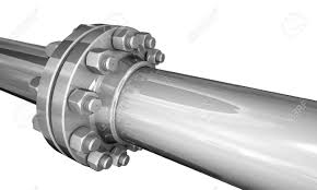
Flange - an external ridge/rim that protrudes radially from the main component. In fluids, two pipes with flanged ends are connected with a gasket to form a seal. |


What is a Seal?
Very broadly, a seal is some device or material used to join two components together and keep anything from passing through them. In the context of pressure feed systems, we want to join our piping, valves, instrumentation, and engine components together, and prevent any fluid from leaking out. We’ll be mainly thinking about two types of seals in Liquid Prop: elastomeric seals (o-rings), and metal-metal seals
Pipe Fitting Table  | O-ring on a Flywheel 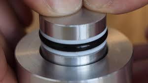 |
Piping
Piping is everywhere in feed systems, and is the main way that fluid is transported between the components. Think of piping as the roads of a fluid highway. In this analogy, our valves are like stop lights, and our engine is the destination. But how do we actually connect our piping together? This is where threads and fittings come into play. Let’s first try to understand the different types of threads commonly used for pipes.
Thread Type | Description | Illustration |
NPS (national pipe straight) | - Straight variant of the National Pipe Thread standard threading. |
|
NPT (national pipe tapered) | - Tapered variant of the National Pipe Thread standard threading. - Used commonly for low to mid level pressure applications. - Tapered attribute allows for increased tightening to prevent leaks. | |
UNF (United National Fine) | - Fine variant of the National Thread Standard. - More threads per length than UNC - Widely used multiple pipe fittings | |
UNC (United National Coarse) | - Coarse Variant of the National Thread Standard. - Widely used for bolts, not so common in pipe fittings |
|
Metric | - Not used too often for us | |
BSP (Brittish Standard Pipe) | - Not used too often for us |


There are other types of pipe thread beyond what is in this table, but they aren’t relevant to us. Actually, we’ll really only be using NPT or UNF for the majority of pipe applications. It is also important for us to identify which thread type a certain pipe or fitting has, but since we largely use NPT and UNF, it is pretty easy to eyeball the taper on NPT threads and distinguish the two.
Fittings
Now that we’ve seen some common thread types, let’s apply them to learning about fittings. A fitting is just a piece of hardware that joins two pieces of pipe, or another fitting, together. Fittings range in complexity, capability, and reliability, but they all share a common goal to prevent leaking in the system and maintain structural integrity at the connection. The table on page 2 defines many different types of fittings, and as you’d guess, they all serve to alter the flow in some way. For the Helios test stand, I’d say we’ve used around 75% of the fitting types in that table. Notice though, from the threads, that these are all what you’d call NPT fittings.
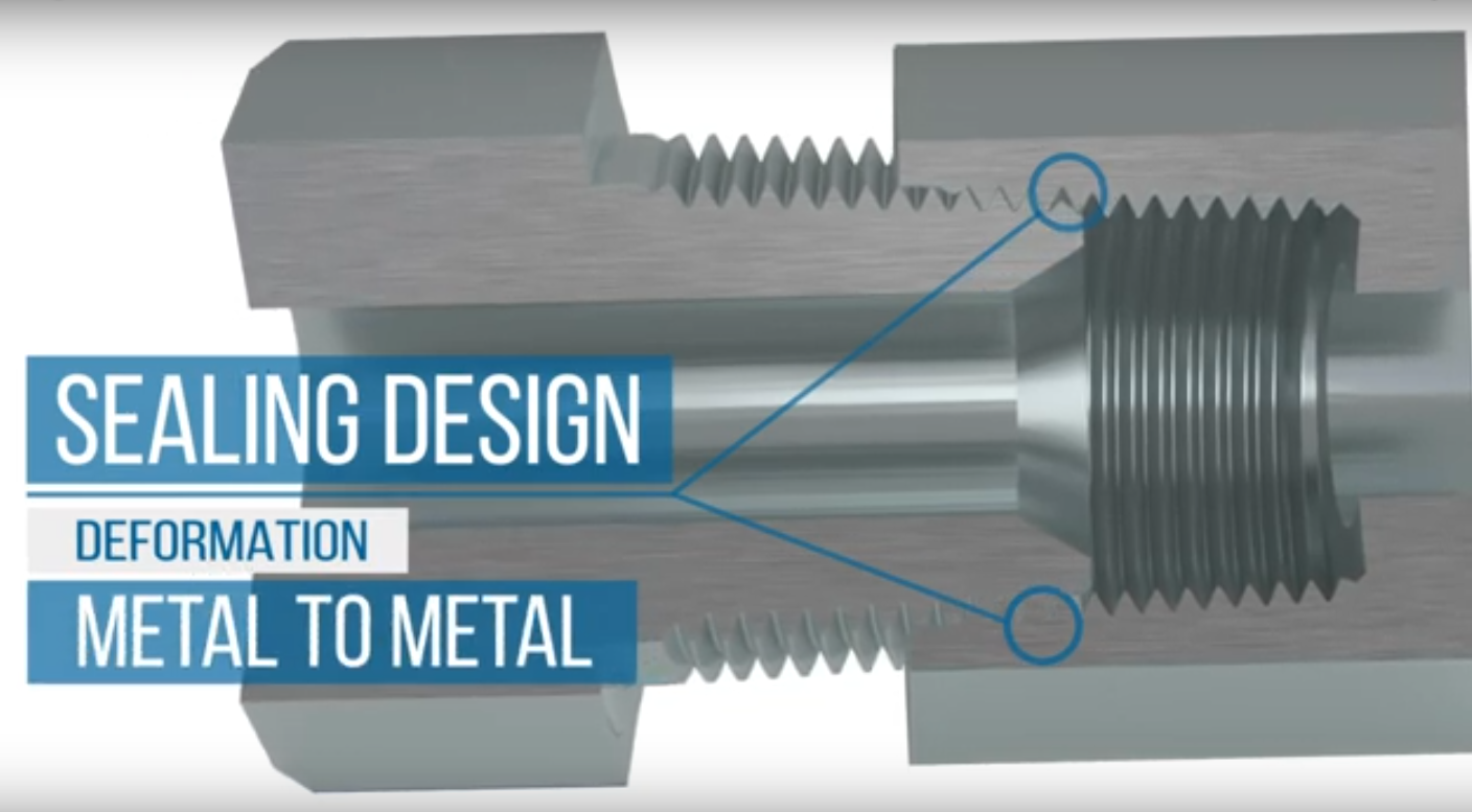
NPT Fittings
NPT fittings provide a simple mechanical connection by deforming the threads upon tightening, creating a metal to metal sealing surface. These fittings have a simple design, and are great for applications which don’t involve frequent retightening. The main weaknesses of NPT fittings is that they become deformed over time with reuse, and they are not easily reorientable. This means that the amount you tighten the fitting will directly affect the orientation. Ex: if you have to tighten another ¼ turn to get the fitting tight enough, you may be inconveniently oriented in your system.

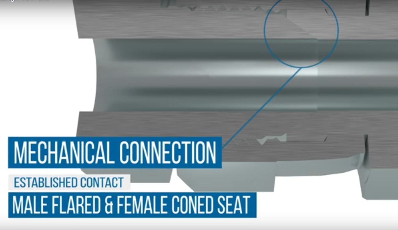
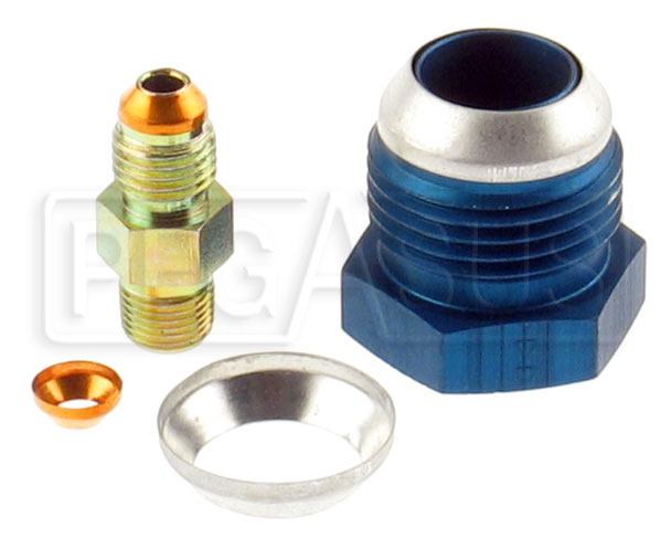
JIC (Joint Industry Council) Fittings, also called AN
JIC fittings typically use UNF thread, and are a commonly used fitting in medium to high pressure fluid applications. Similar to NPT, JIC fittings also provide a metal to metal sealing face. Instead of thread deformation, JIC fittings create a compressive seal at the 37 degree seat when tightened. This makes JIC fittings much more replaceable, for the threads will not wear significantly over time. Additionally, the two-piece female component of JIC fittings allow for easy orientation before the connection is fully tightened. One consideration that detracts from the use of JIC is that they are more mechanically complex, and often more expensive than NPT fittings.
*note: JIC fittings may also be referred to as AN (Army-Navy). AN fittings have identical design dimensions as JIC, but are manufactured with tighter tolerances.
JIC fittings can also be used to connect piping components to tubing. In this scenario, the non-threaded female component is replaced with a piece of flared tubing and accompanying sleeve.

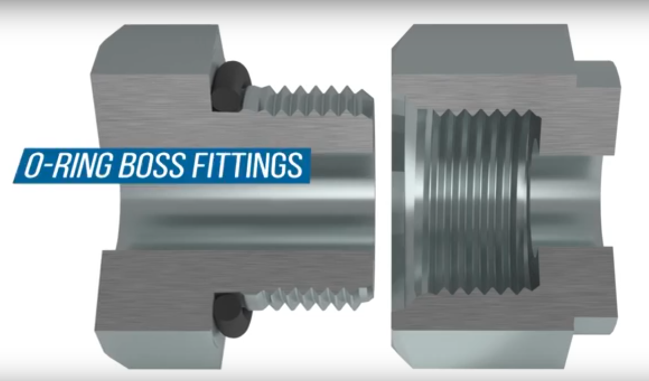
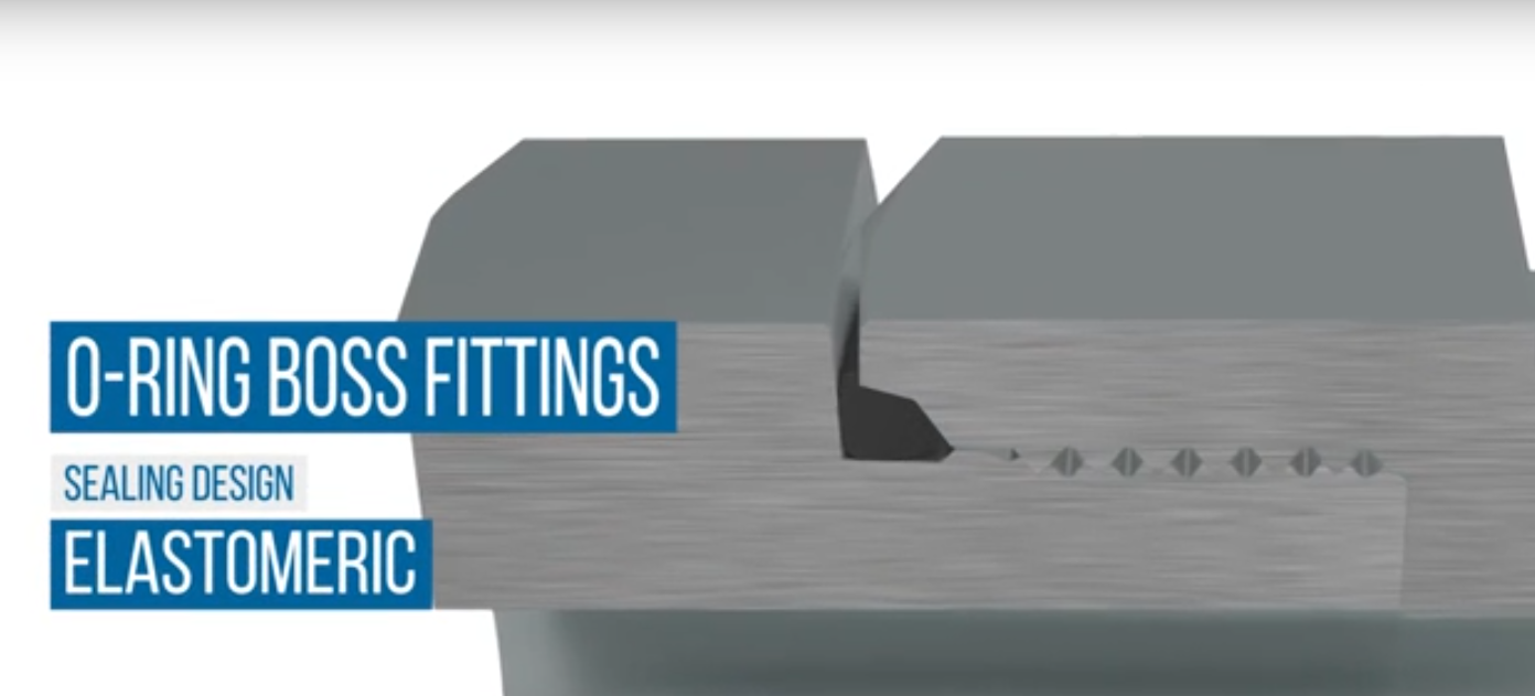
ORB (O-Ring Boss) Fittings
ORB fittings typically use UNF thread, are commonly used in medium to high pressure fluid applications. The male components of ORB fittings are flat face, and feature an o-ring at the head of the threaded section. The seal is created when the fitting is tightened, and the chamfer of the female piece compresses the o-ring, creating a type of crush seal (we’ll talk about this soon). Because the o-ring is the sealing factor, ORB fittings can be more easily reused without mechanical wear. Adjustable orientation variants of ORB fittings are also common, which allow for much easier installation and alignment. The main disadvantage to ORG fittings is that the relevant temperature capability is limited to that of the o-ring.

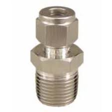
CGA (Compressible Gas Association) Fittings
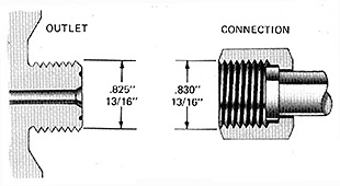
CGA fittings are used to connect to the outlets of compressed gas tanks, and use special NGO (National Gas Outlet) thread. There are many different types of CGA fittings, which vary based on the gas that will be used and the tank’s outlet interface. The Helios test stand uses Compressed Nitrogen gas, and we interface with the outlet of the tank using a CGA-580 fitting, which is attached to the regulator. Our propellant tanks also require CGA-320 fittings on the outlet.
CGA-580 Design | CGA-320 Design |

Compression Fittings (double-ferrule)Compression fittings are widely used in high pressure fluid systems to connect tubing and piping. These fittings include three components, the body, nut, and ferrule(s). The body features an inner bore that matches the radius of the tube being joined. When the tube is inserted into the body and the nut is tightened, the body’s cone seals with the ferrule, creating a seal, and the ferrules are pushed radially inward, compressing the tube and keeping it in place. Compression fittings are great for reusability, and don’t have the temperature limitations from o-ring usage. When installing compression fittings, it’s important that the tubing you insert has been deburred, cleaned, and sanded into a uniform surface |


Auxiliary Piping Components
Maintaining the health of piping and fitting components is crucial for system reliability and longevity. A variety of different auxiliary components and additives are used to ensure this health.
PTFE (Polytetrafluoroethylene) Tape, also called Teflon TapeTeflon tape is a necessity for pipe fittings, particularly NPT fittings. Applying PTFE tape to the threads of the fittings before installation helps slow thread wear, and helps fill slight imperfections in the thread. PTFE is also an amazing material! It works well in extremely high and low temperatures, and is extremely chemically resistant. |

Conical Crush SealsFor JIC fitting applications, conical crush seals are often used to repair and prevent any irregularities in the mating surface. These conicals are thin metallic gaskets that are placed over the flared part of a male JIC fitting. Using conicals will greatly increase the reusability of flared fittings |
LubricantsLubricants are often used on pipe threading to ease installation, help with sealing, and reduce wear over time. As a general rule of thumb, lubrication should always be used on metal to metal threading connections if teflon tape is not used. Two commonly used lubricants are Krytox and DC 111. Krytox is used for general piping application, and is necessary when components are exposed to cryogenic temperatures. DC 111 is used for components exposed to vacuum environments (very low pressures) |
Consider a fluid system that is exposed to very high temperatures, and requires frequent untightening and retightening of components for inspection. Answer the following:
What would be the best type of fittings to use and why?
What should we do to ensure that the fittings stay healthy and effective after successive reuse?
O-Ring Seal
Here’s a pretty good definition of an o-ring:
“An O-ring is a doughnut-shaped object or torus. The opposite sides of an O-ring are squeezed between the walls of the cavity or “gland” into which the O-ring is installed. The resulting zero clearance within the gland provides an effective seal, blocking the flow of liquids or gases through the gland’s internal passage.”
Okay, let’s decompose this a bit. The o-ring itself is a ring of elastomeric material, that is compressed between two pieces of material to create a seal. The groove is the annular cavity machined into one piece of metal. The clearance is the small distance between the two surfaces, which may be zero. The combination of the groove depth and clearance is the gland depth. The figure to the right shows that a properly designed sealing system incorporates some degree of initial O-ring compression. At atmospheric pressure though, only the resiliency of the compressed O-ring provides the seal. However, as system pressure activates the seal, the O-ring is forced to the low pressure side of the gland. Designed to deform, the O-ring “flows” to fill the diametrical clearance and blocks any further leakage. |
The figure below illustrates the effect of pressure as it pushes the o-ring to seal the clearance gap.

Types of O-Ring Seals
There’s many different ways that o-ring seals are used, all with different applications. The main differentiations are whether the seal is a radial or face seal (flange design), and whether it is static or dynamic. Here’s a few common o-ring designs:
Seal Type | Illustration |
Face (Static) |
|
Radial (Static) Maximum 1500psi recommended | |
Crush (Static) (used for ORB fittings) | |
Piston (Dynamic) Maximum 1500psi recommended | |
Rod (Dynamic) Maximum 1500psi recommended | |
Rotary (Dynamic) Maximum 900psi recommended |


O-Ring Geometry
There’s two main considerations when designing the geometry of the o-ring: stretch and squeeze. When an o-ring is installed in a groove, some small amount of stretch should be required to fit it in. There should also be some amount that the o-ring is squeezed when the sealing surface is made. Here are some rules of thumb for basic O-ring gland/groove design:
Maintain a % squeeze on the o-ring. About 10-40% for static seals, and no more than about 30% for dynamic seals.
At least 75% of the seal cross-section should be contained within the groove to ensure that the o-ring does not roll, extrude, or get squeezed out of the seal even under system pressure.
The maximum o-ring volume should be no more than about 90% of the minimum gland volume.
Choose the o-ring size that most closely fits the diameter you are sealing around.
O-ring Materials
Choosing the correct o-ring material will depend on the application. There’s dozens of different materials available, and all with different specifications for operating temperatures and chemical compatibility. Your best bet is to look at a table, and make sure you know the expected operating temperatures and pressures the seal will be exposed to.
Effect of pressure
The pressure difference across an o-ring seal causes the o-ring to be pushed inward or outward, depending on which side has higher pressure. If the pressure is too high, the o-ring will extrude out too much, preventing an effective seal and causing damage. Radial seals specifically are not recommended to exceed around 1500psi of pressure. To prevent damage from overpressurization, you might have to use an o-ring with increased hardness, reduce the clearance length of the seal, or use a second o-ring.
good |
bad |

Effect of Surface Finish
Precise, accurate, and clean machining of o-ring grooves is crucial to avoiding degradation over time. Make sure seal grooves are free for debris or gunk before installing the o-ring.
Choosing an O-ring
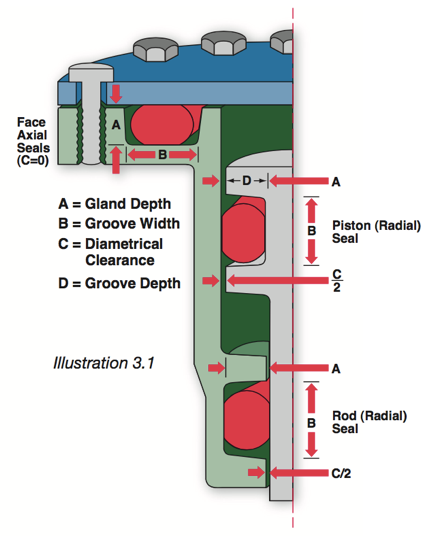
Okay, so I just told you about a bunch of different factors for o-ring seal design, but how do you actually find the right dimensions for the grooves and gland? There are some basic equations for calculating base dimensions, but the best thing to do is just look them up in a table. These tables are everywhere (they’re in the o-ring manuals), and they’re not too hard to read if you know your o-ring vocabulary. Let’s look at the tables now and see how we can design our glands/grooves, using the below diagrams for dimensional reference.

Static Axial Seal Illustrations


Static Radial Seal Illustration
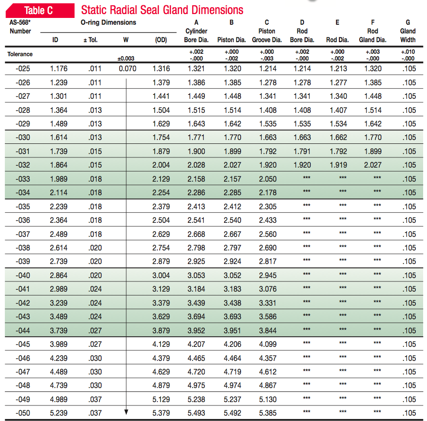

If we know the OD of our piping, and which side the pressure is (most often internal) we can first choose our A diameter, which will be the OD of our groove. Our groove ID will then be A - 2G. The “AS-568” number is the standardized size of the o-ring, which you will choose when purchasing from a vendor
Questions
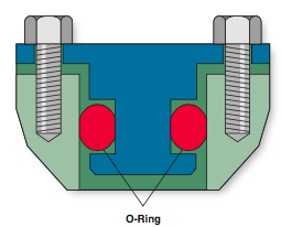
A. Consider two 1.5 inch diameter pipes that we plan to connect with a flange joint (pictured below). Answer the following: i. What type of seal should we use? ii. What size o-ring should we use? Hint: the groove ID is not the pipe diameter! iii. What is the required groove depth? iv. What is the required gland depth? |
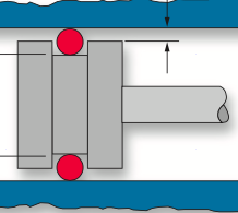
B. Now let’s say we are designing the forward closure for the Phoenix booster’s motor case (pictured below). Assume that the ID of the motor case lining is 4.2 inch. Answer the following:
i. What type of seal should we use?
ii. What size o-ring should we use?
iii. What is the required groove depth?
iv. What is the required gland depth?
v. Turns out that the pressure inside the motor due to the burning propellant will exceed 1500psi. Why is this bad, and what can we do to fix/improve our seal?

Return to Learning Curriculum