The nozzle is the orifice through which all exhaust exits the motor. At least so long as you’ve made everything right.
Simple nozzles are made from a single piece of graphite or phenolic, heat resistant materials that can handle the exhaust. They need to be sealed to the case so exhaust only goes through the throat. The throat is important, as it factors into determining thrust, chamber pressure, and other factors. It has a step into the liner which should be a tight fit but not sealed.

The most important thing the nozzle does is have convergent and divergent sections, which chokes the flow at the throat to speed up the exhaust, then expands to match ambient pressure. The convergent section, which directs exhaust to the throat, has a half angle of 45-75 degrees. The divergent section expands the exhaust to ambient pressure and has a half angle of around 15 degrees.

Here is a more complicated type of nozzle, with a graphite throat to handle the highest heat at the throat, phenolic insulation and expansion section, and an aluminum carrier. This design is lighter than the simpler design, has better insulation, protects the aluminum parts, and requires less graphite machining. However, phenolic isn’t much easier to machine than graphite, and this is obviously a more complex part. So deciding which part to use is a more involved decision that requires careful consideration.

When designing a nozzle, it is important to think about how to make it as minimal parts as possible while keeping it relatively easy to machine. For the past two rockets (Medusa and Pheonix), this constituted 4 pieces in total: An aluminum carrier, phenolic insert, graphite insert, phenolic top. Medusa nozzles can be viewed here. The entrance diameter inside of the motor should be the same as the outside diameter of the propellant grain to allow all the gas to flow into the nozzle. Much of the nozzle design depends on the propellant geometry designed in OpenMotor or Burnsim. Those programs allow you to design the full nozzle. We typically do a 45-60 degree convergence with a 15 degree divergence angle. It is the easiest way to achieve the maximum efficiency of the nozzle. The graphite should be taking the majority of the force and fire as it is a good insulator and hard. This means the throat should be made out of graphite. It should also have some thickness as it needs to be able to take the force of the gasses. The phenolic should make up the majority as it is lightweight. The joint between the components should have a slanted portion then flat for an effective seal using rtv. The aluminum carrier should still have enough thickness for o-rings and the bolts.
Before you have fire shooting out through the nozzles you’ve made, you need to light the fire. The only safe way to light any motor is electrically, so you need a device that converts an electric signal into heat to ignite the motor. The goal of this device is to raise the chamber pressure and temperature to a point where propellant sustains combustion. This device is nearly always installed at the forward end. The image shows a configuration for a test firing, as shown by the nozzle pointing upwards, but the idea still holds

The igniter is ejected from the motor once used, unless it is mounted to the forward closure. In the image, you can see just how powerfully it is thrown out during a static fire. There are many possible compositions and designs

Two types of igniters are shown. A bridgewire passes a lot of current through a thin wire, heating it up to lead to ignition. An e-match uses resistive heating to ignite a portion of initiator, which then ignites the fuel. We augment it using pieces of scrap solid fuel.

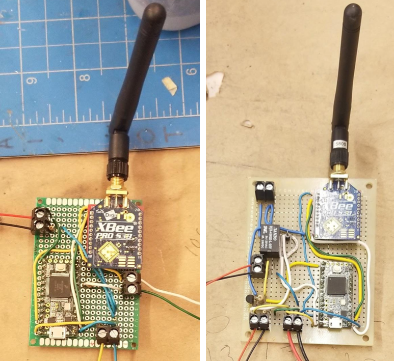
The ignition system is what produces the electrical signal that starts the igniter. It can be as simple as a battery and a long wire, but because long wires are annoying to deal with, we often use a wireless system, like the custom one in the photo.
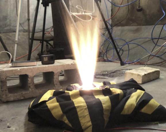
The head end ignition mechanism is what we use to ignite the second stage of the rocket. Since igniting at high altitudes and the corresponding low pressure is hard, we needed to develop a robust ignition method for upper stages. This system had to be triggered by the flight computer, function at vacuum conditions, ignite motors up to “O” class, and ignites in under a second. The design of our head end ignition system, shown in the picture, is what fulfills these requirements. It is, in essence, a mini rocket motor, with a chunk of propellant grain, which is first ignited, and the exhaust flows through nozzles in the phenolic to in turn ignite the main rocket.

The head end igniter is shown firing in the picture below
The forward closure is the component that we use to prevent exhaust from leaving the forward end. It is typically made of Aluminum 6061. We use O-rings to seal against the case and liner. It is retained by the forward retention ring. Though not always required, an insulation disc is often installed onto the aft face of the Forward Closure. The forward closure is also the most common spot to install instruments into the motor, like pressure transducers and thermocouples.

In order to seal the forward closure to the case, we use o-rings installed into grooves on the forward closure to keep combustion products in the liner and pressure in the case. The seal is often done with multiple o-rings for redundancy

Various pieces of instrumentation can be installed to the forward closure. Here, we see a bolt threaded into the forward closure to transfer thrust to a load cell, and a tapped hole for the pressure transducer.
