
Procedure Overview
Below is the detailed procedure for how the first flight candidate fin can was manufactured. A phenolic tube (insulation from motor case) was overwrapped with 3 layers of carbon fiber (structural support). After the fins were manufactued (see "Hermes 2 Fin Design"), they were attached to the tube and 6 plies of increasing size were added to each of the 4 sides of the fin can in the tip-to-tip layup. After vacuum-bagging and room temperature curing for 24 hours, the fin can was oven-cured. Post-processing (sanding, painting, etc.) was not done because we wanted to manufacture a second flight candidate fin can to make some improvements, namely concerning the misalignment between the phenolic leading edge and the tip-to-tip plies.
1. Tube Preparation
Sanded inside of tube by hand with 60-grit sandpaper, went over with 220-grit (this took a long time so for next time ordered a flapper wheel, 60-grit)
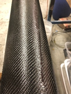
Tube layup: 3 layers of carbon fiber (cut piece slightly longer than necessary for some wiggle room), did not oven cure because of time constraints and whole thing oven cured in the end.
-Used Systems 3000 epoxy but didn't oven cure after layup
2. Root Bond and Root Fillet
Did root bond using 5-minute. fin can jig needs to be improved
AFTER root bond, attached phenolic LE to G10 fin core (did after root bond because phenolic wouldn't have fit in the fin can jig)
Root fillet (West Systems fast hardener + colloidal silica)
3. Carbon Fiber Cut-outs for Tip-to-tip Layup
The carbon fiber cutouts are the pieces of carbon fiber used in the tip-to-tip layup, which consists of laying plies from the tip of one fin, over the tube in between them, over the tip of the next fin (and repeating for the other three sides).
Quentin designed CF cutouts (6 sizes --> small to large)
Lasercut CF cutout - went well but largest cutout size did not fit in the laser cutter

4. Preparation of Vacuum Bagging Materials
Prepared vacuum bagging materials
5. Tip-to-tip Layup
Mark centerlines on tube and CF cutouts
CF didn't meet up in certain places (ends of tubes, some were barely large enough to cover the fins)
Only had one ply going all the way to the end - saw exposed G10
Triangle of exposed area near the fins --> adjust size of cutouts
Below is a table showing the mass of each cutout size. One of each size was measured, so this is technically not an "average" mass, but we expect that since the laser cutter was used to make the cutouts, the mass of each size is more or less the same.
| Layer Size | Dry mass of one layer |
|---|---|
| 1 (smallest cutout size) | 20g |
| 2 | 22g |
| 3 | 23g |
| 4 | 26g |
| 5 | 33g |
| 6 (largest) | 39g |
| Total mass of all cutouts (6 sizes x 4) | 652g |
6. Vacuum Bagging
Vacuum bag was 32 x 38" (this is TOO BIG, make smaller next time. For the test fin can though the bagging was too SMALL, so find a good middle ground)


7. Oven Cure (ATTACH SOP)
Positioned fin can horizontally as shown, because there wasn't enough vertical space in the oven we used. This may have caused the fins to splay (weight of the tube + epoxy loosening --> fins move), so in the future we should position it vertically.

8. Post-processing
Vacuum bagging materials were difficult to remove, but not impossible
Used Dremel to get rid of CF on trailing edge and either end of tube (in future, taper trailing edge of G10 to get smoother layup quality)
Sanded CF on leading edge
