Overview
Due to materially inefficient casting procedures, the team had an excess of thermal liners for 98mm motors. This lead to the idea to attempt a monolithic grain casting directly in the thermal liner.
Simulations
Sam A designed a Burnsim file for the motor, uploaded here.
Manufacturing
The motor is designed to utilize a 98mm thermal liner from RCS, a hot-wired foam core, 3D printed end caps, and 12.5 lbs of propellant. This load should be compatible with any appropriate case.
Making the Mandrels
The mandrels were designed in burnsim, and then CADed in Solidworks. The face of the grain was exported as a .dxf file from solidworks. The .dxf was run through this python script to generate a .dat file for the foam cutters. The foam cutter was run at .03 in/s at 20V to produce the mandrels. These values were determined by experimentation.
Making the Caps
The mandrel is held in place by 2 3D printed end caps. The aft mandrel fits over the casting tube and can be taped in place to seal that end. The foam mandrel is epoxied into the aft cap. The forward mandrel cap slides inside the liner tube and is designed to sit flush against the propellant. The mandrel slides through it. The forward cap contains captive nuts to allow it to be pulled out of place. Both of the caps were 3D printed from ABS plastic to allow them to be dissolved with Acetone should other extraction techniques fail. Both caps are designed to be an appropriate thickness so that the nozzle and seal disk can seat fully in the liner. Future improvements might include printing the aft cap to allow the propellant to match the taper of the nozzle converging section, or machining these from aluminum to make them more robust and extractable.
Nozzle End Madrel Cover.SLDPRT
Cutting the Liner to Length
The liner was cut to 30 inches long for 28.25 in of propellant. The madrel caps are .6 inches thick. This should leave the propellant section slightly long to be trimmed back to the correct length. The inside of the liner was abraded with 150 grit sandpaper to improve adhesion of the propellant to the liner and avoid a debonding failure which could lead to the outside surface burning, and a rapid, unscheduled disassembly. The inside of the liner was then cleaned with Acetone to provide a good surface to bond the propellant to.
Casting
The liner was measured to be 29.75 inches long and weighs 1.56 lb. The ID of the liner was measured to be 3.384 inches. This will serve as the OD of the propellant slug. The foam mandrel was measure to have a cylinder diameter of .956 inches. There are six fins, each .2 inches thick, protruding .474 inches from the cylinder. This is 215.06 in3 of propellant volume.
The foam core was expoxied into the aft casting cap with 5-minute epoxy. The 3D printed caps were coated with frekote.
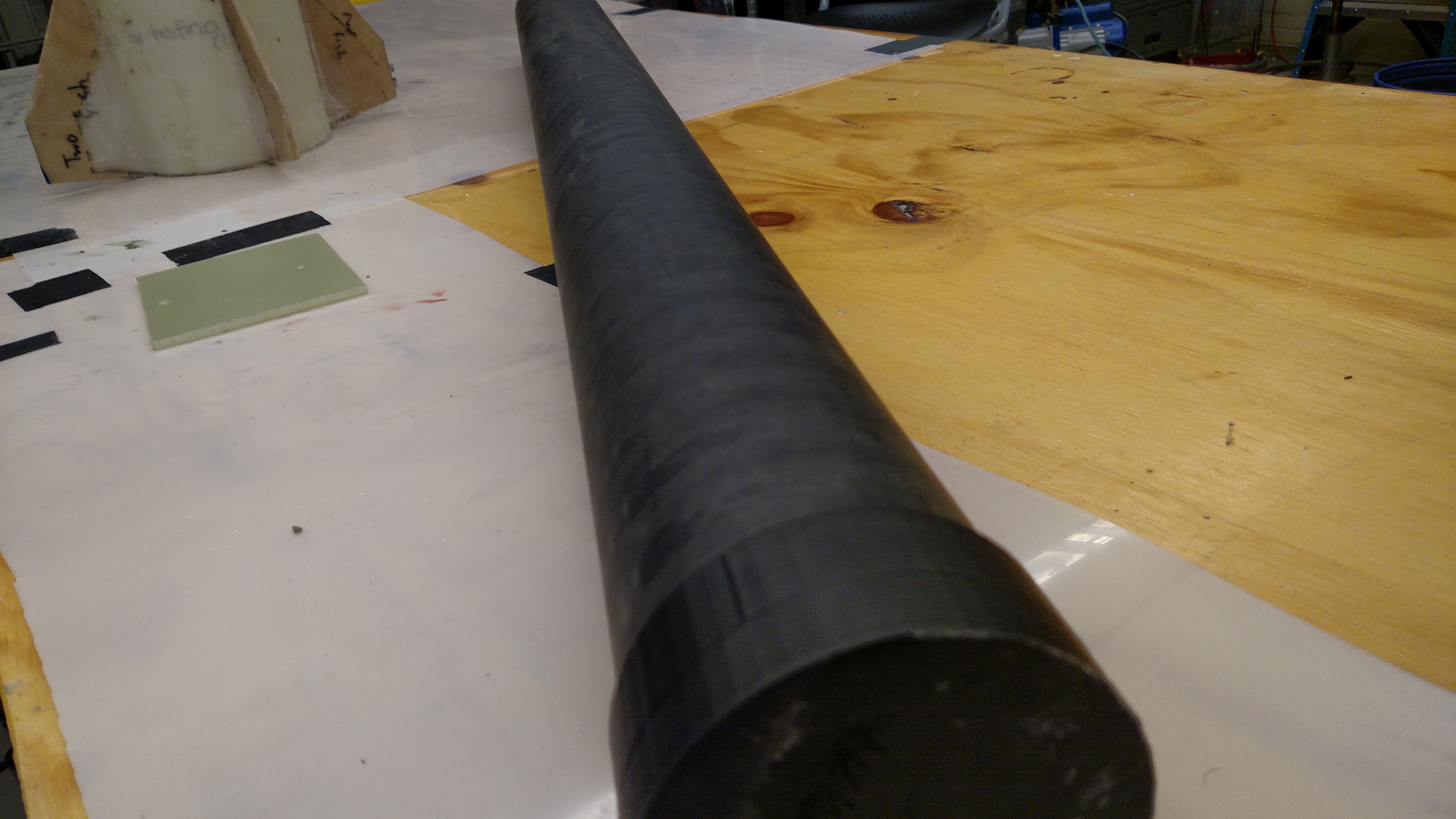
During casting it was noted that the foam was quite flexible and could be bent easily. It was suggested to add a carbon fiber rod for additional stiffness, but after demolding, it appears to have not been an issue. The mass of the propellant and liner post demolding is 14.46 lbs. The liner weighs 1.532 lbs. The total propellant mass is 12.93 lbs. This suggests a density of 1,663.56 kg/m3.
Demolding
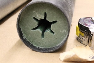
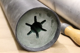
The motor was demolded by acetone. Acetone was poured through the core, and into the end caps after they were pulled most of the way off . The top end of the motor did not come out clean, as the propellant cured, it shrank, but some remained adhered to the top cap. This was cut off. A very manual process was then undertaken to create a .5 in recess for accomodating the forward closure.This started by using an exacto to shave in a spiral patter about .05 in at a time to get the the required depth. An exacto knife was further used to clean the face. This face was then sanded as smooth as possible. The resulting faces are pictured below.
Assembling the Motor
TBD
Firing the Motor
Main article here.