In 2017, we were required to make our own nosecone. To maintain consistency with the rest of the rocket, we decided to use a fiberglass/epoxy composite. See this article about the nose cone mold.
The actual nose cone layup was very challenging and tended to create suboptimal parts; however, with enough layers, they were deemed sufficient.
- We cut out many rectangles of fiberglass, in several sizes. We probably cut approximately 30 each of 3"x4", 4"x8", and 10"x12", as well as 6 strips of 3"x48".
- We laid out the mold halves next to each other, mold side up and pointing the same way.
- We coated the mold halves in 3-4 layers of mold release.
- We coated the nose cone part of the mold with gelcoat to provide a better surface finish. We did not have enough remaining gelcoat for the coupler section, but the mylar provided a superior surface finish, making the gel coat unnecessary.
- We placed 2 long strips along the right side of each mold, to provide strength across the parting line.
- We placed a strip of wax paper on the left side of each mold, covering about 1-2" of the mold surface.
- We placed fiberglass rectangles on the mold, and squeegeed epoxy onto the fabric until we had completed 5 layers near the tip, 7 layers near the base and 9 layers in the coupler.
- Since the coupler was the right size, 7 layers would be more than sufficient. We should run tests to determine how few plies are necessary for the nose cone, and put fewer (maybe 3) plies at the tip, so this section fits together better when the mold is fully assembled.
- We folded over the glass on the left side of the mold to make space, and removed the wax paper.
- We put together the mold halves, taking care to insert the free fiberglass strip under the folded-over fiberglass so that they overlapped. A useful trick here was to use scrap aluminum tubing as a shim to keep the mold halves apart while we reached our hands into the parting line.
- We used the stick (accessory tool pictured below) to fold back the folded-over fiberglass, such that the layers overlapped.
- We used the stick to apply 4 more strips of fabric on the inside of the nosecone; 2 on either side.
- We moved the nosecone to the floor, with the cone pointing downwards.
- We used two very large clamps to clamp together the coupler section, and some weights to push the rest of the mold together.
- We used two balloons to apply pressure to the composite as it cured; the balloons were inflated with the vacuum pump because we were all wearing respirators.
- We left the part to cure for 48 hours, then removed it.
 |  |  |  |  |
|---|---|---|---|---|
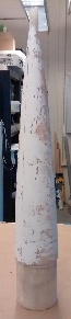
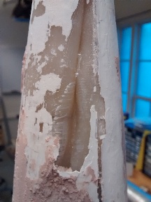
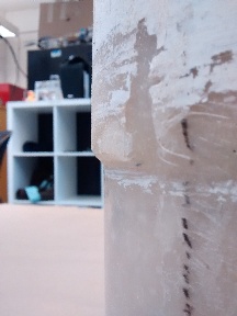
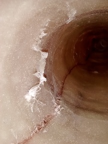
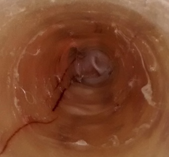
The second nosecone from the MDF mold. | A large crease near the tip of the nosecone. To avoid this, we should use fewer plies at the tip. | The base of the nosecone is not a sharp edge and required some sanding to seat on the tubes properly. | A small tuft near the coupler section, where we were unable to compress the fabric during cure. | Large tufts near the tip of the nosecone. |
Of course, there were several recurring issues arising in the parts:
- Creases near the tip of the nose cone at the parting line, because there was too much fabric to make it overlap well and manipulating the fabric was difficult.
- Stray tufts of fiberglass inside the nosecone: because we weren't able to reach the end of the nosecone, the tip of the nosecone was blocked off by stray tufts of fiberglass that weren't smoothed out. The tufts near the tip were much more of an issue than the tufts near the coupler section.
In the future, there are a few things we would like to change:
- Since the coupler did not need to sanded in order to fit inside the tubes, a 7-ply coupler should be plenty.
- Fewer plies near the tip of the nose cone should be tested so that the mold fits together better.
- The number of plies should be decreased after we complete our structural testing