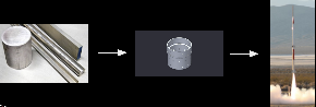
So, in previous lectures, you’ve heard about our propellants and our designs. Now, it's time to learn how to turn raw materials and cad drawings into actual objects
These are the spaces on campus where we work to machine parts. Some of this might be old information, but generally this is where we go for machining.
- N51 (Milkdrop Shop & Area 51)
- Gelb (Beneath Unified Lounge)
- The Deep (Basement of Building 37)
- New Lab (Building 17)
Three of the big tools we use are lathes, mills, and bandsaws. Lathes are best for making cylindrically symmetrical parts. They spin the stock, and we bring cutting tools into the piece at various locations to cut away our part. Since our rocket is a cylinder, we make most of our parts on this machine.

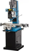
The mill is useful for fine details in parts, and most can be programmed through CNC. The tool bit is above, and can move up and down, and the part is placed on a platform that moves on two axis, resulting in three axes of movement. We can attach a tool called a radial indexer to a mill, which allows for holes to be drilled at precise angles.
The bandsaw is a pretty simple tool. Its just a saw that chops down, and which we use to cut our stock to size. Something important to know is that all of these tools need training to be used, since they can be dangerous if used wrong. However, they’re pretty easy to learn how to use.
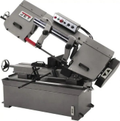
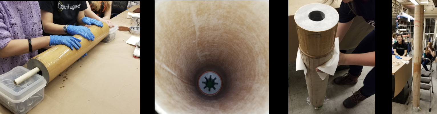
When we buy materials, we usually get extruded rods that need to be cut to size for use. We usually use the horizontal bandsaw to cut stock to size. We do this for aluminum and graphite, but not for phenolic, a type of fiberglass that comes in sheets and blocks. Since it doesn't come as extruded material, we use a laser cutter instead. We never cut our stock exactly to size. Instead, we always leave a little extra to correct during manufacturing. You can always cut away extra material, but you can't add missing material.

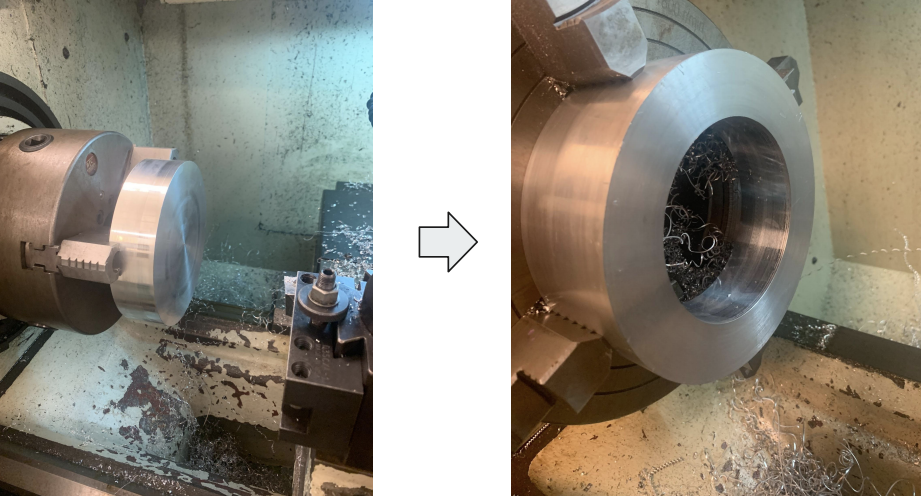
When turning on the lathe, before anything else, we have to consider how the material’s toughness and size will determine how fast we want the spindle to rotate. Turning itself has various steps. The first is facing. This is where we create flat surfaces on the part, in order to zero out the operation, and to be able to precisely make the desired shape. We take a facing tool and have it go across the spinning part until we get a perfectly flat surface. Boring is how we cut central holes, going into the part itself. Angles and curves we make by moving the tool in two axes at once. Finishing is the last step, where we smooth everything out, sand and so on.
The radial indexer is a tool mounted on the mill that allows the user to equally space features on a cylindrical surface. Its useful for making radial bolt holes. The holes on the index plate allow the user to rotate the part, held by the radial indexer, by a precise angle, so we can evenly space holes.

Once all the individual parts are made, we have to assemble them. Our parts are attached to each other and the rocket with one of two ways. The first is by gluing. We use a silicone rubber glue called RTV that can handle high temperature. We also use bolts, usually with metal components. Before assembling, you must be sure to double check measurements, and make sure everything is within tolerances. Also make sure to fit check your parts. Make sure they fit together before you start gluing.
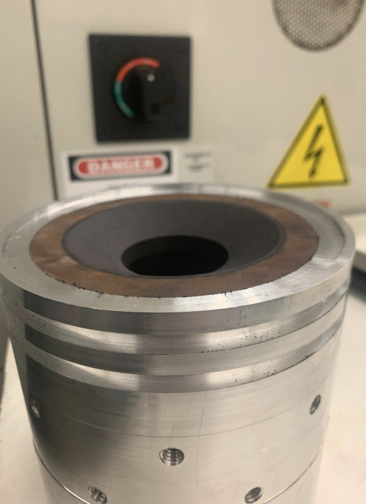
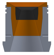
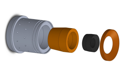
One example is machining the booster nozzle assembly. These are the four parts of the nozzle assembly. We have the aluminum nozzle carrier, the phenolic insert, the graphite insert, which has the throat of the nozzle, and the phenolic nozzle cap. To machine this, we would use the bandsaw to cut stock to size, the lathe to make cylindrically symmetric cuts, and the radial indexer to make the bolt holes. Here is a rough procedure of what we would do for the nozzle carrier, for example. 1. Hold from bottom with material left over. 2 face. 3. Cut down outside 4. Cut notches 5. Bore in hole 6.Renove and take to radial indexer to bore out holes for bolts 7. Cutoff part used to hold 8. Put in lathe other way. 9. Cut outer notch 10. Cut outer angle.
Now, we move onto assembling the whole rocket motor
Dry Fit
Grainbond
Assemble nozzle and FC with RTV, set aside to cure
Grease and install o-rings in the nozzle and FC
Coat the liner with grease and install into case
Install closures into case and secure with bolts
Seal nozzle if storing for more than a day or two
A dry fit is the first step in the assembly process. We put together all the components without glue or grease. This makes sure everything can actually fit together, and verifies the dimensions. Always do this before final assembly to avoid costly mistakes
The next step is grain bonding. If the motor is made of separate grains, you must bond the m to the liner. We’ve had good results using laminating epoxy and RTV. Before assembly, weigh the grains, and include a spacer o ring between grains to allow the faces to burn.

After this, we assemble the nozzle. We glue the graphite insert into the phenolic liner, and the liner to the aluminum holder. We add o-rings to ensure a proper seal, and insert that to the motor case, and screw everything together

The forward closure follows a similar assembly procedure to the nozzle

Then, we slide and glue in the liner and grains into the case

This is the final assembled motor, with all the grains, nozzle, and forward closure attached securely.