Introduction
The Osiris engine is a liquid bipropellant rocket engine featuring active throttle control and thrust vectoring, designed for the Collegiate Propulsive Lander Challenge (CPLC). It uses isopropanol (IPA) as fuel and nitrous oxide (N₂O) as oxidizer. The engine is engineered to meet the following key performance specifications:
Mixture Ratio: 2.75
Burn Time: ~14 seconds at full throttle
Throttle Range: 32–100%
Chamber Material: GrCop-42
Total Impulse: 38,754 N·s
To ensure Osiris can reliably meet these requirements, a thorough design and analysis cycle is required. This page documents the process used by the MIT Rocket Team to design the Osiris engine to a level suitable for passing a Critical Design Review (CDR).
Nozzle Geometry
Fuel Inlet Manifold
To maintain the chamber and nozzle wall temperatures required, an even distribution (equal mass flow) of fuel through the regenerative cooling channels is critical. To do this we look at the equation ṁ = 𝜌*A*V. Density is constant because the working fluid is a liquid, so 𝜌 = constant. We want the velocity to be constant through the manifold to maintain even distribution, and so our variable to change here is area "A". To decide how the manifold area changes, we first treat this manifold as two half-manifolds (splitting the two such that only half of the inlet port is in either half), with the other half simply being a mirror image of the first:

We then say that the half-manifold area at the last channel (180° from port) is going to be the same as the channel area "Aₒ", times some constant k (with k setting the difference between channel and manifold velocity). Then moving from "back" to "front" we can say that the area of the half-manifold is going to be 2* k * Aₒ, since this has to be double the mass flow of the previous channel. Thus we can generalize and say: Aₘ(n) = k * Aₒ * n. Where n is the number of channels (counted on the half-manifold) away from the "back" and Aₘ(n) is the area of the half-manifold. When creating a semi-circular manifold, the radius of the manifold is simply given by: Rₘ = √(k*Aₒ * n / 𝜋). This can then be modeled as a series of n semicircles which are lofted together and mirrored to create the CAD geometry.
The surface roughness effects on flow distribution (losses to boundary layer development and such) were not considered in this analysis, which greatly simplified the design. The validity of this assumption will be verified empirically by routing each channel into individual containers and measuring the mass flow distribution.
As of May 7th, 2026 the part is being actively fabricated by a 3rd party.
Cooling Channels
A critical aspect of rocket engine design is determining how the combustion chamber will be cooled. Temperatures inside a high-performance rocket engine can reach over 6000°F (≈3315°C)—hotter than molten lava! At these temperatures, proper material selection, structural analysis, and cooling-geometry design become essential to ensuring engine survivability. Although many cooling methods exist, the final Osiris engine design uses a regeneratively cooled chamber featuring 40 cooling channels running along the chamber wall. These channels allow propellants (fuel or oxidizer) to absorb heat from the chamber before being injected into the combustion zone, improving both thermal management and overall engine efficiency. The following sections outline the process used to develop this cooling-channel geometry, including the structural and thermal analyses performed, the CEA/RPA performance modeling, and the iterative FEA workflow used to verify the design.
Initial Design (RPA)
Rocket Propulsion Analysis (RPA) was used for initial thermal and geometrical characterizations of the chamber. RPA takes performance parameters for the engine along with the geometry of the regenerative cooling channels, the mass flow of fuel through the channels, the thermal conductivity of the chamber material, and the mass flow dedicated to film cooling the chamber. For this project, the Bartz equation was selected as it provides a conservative estimate for the cooling performance. RPA uses the Bartz equation as the underlying method to calculate the temperature distribution, which is why it was used for this initial design and analysis. To set the software up, we inputted all our performance specifications and conditions, such as the fuel and oxidizer we are using, OF ratio, and mass flow. Lots of these values were taken from initial CEA analysis. This is inputted under the "Initial Data" and "Engine Specification" tabs.
Then, the cooling channels were focused on, found under "Engine Design" → "Thermal Analysis" → "Thrust Chamber Cooling". When designing the cooling channels, iterations had to be done between specific geometries (rib height and width), and # of cooling channels. Before doing this iteration, however, a number of manufacturing limitations were set by the company that was printing our engine. Osiris will be additively manufactured using LPBF, and the following geometric limitations were given to us:
- Inner wall thickness: no less than 1mm
- Size of channels: no less than 1.5x1.5 (for de-powdering purposes)
With this in mind let's first go over film cooling. In short, this is a type of cooling done where a thin film of propellant (either fuel or oxidizer) is injected onto the inner surface of the chamber to provide a protective thermal barrier against the high heat fluxes of the chamber. Since our team decided to have film cooling alongside regenerative cooling, as done in most rocket engines, under "Cooling Segments", we inputted film cooling by allocating a fraction of the fuel mass flow towards film cooling.

We then added the regenerative cooling channel design. This process involved setting a rib height-width ratio, iterating over that ratio for different sizes, and also changing the amount of cooling channels. For each input, we would analyze the data in the "Thermal Analysis" tab, checking heat flux, hot-gas wall temp, coolant pressure, etc. These were values used in the next section to determine if the chamber can withstand the engine firing with these cooling channel specifications.


Once this was done, and we were satisfied with the outputs of the thermal data, we could then export the chamber design given into a CAD software such as Solidworks, using it as a base to design the rest of the TCA.
This process was repeated when doing throttling calcs for our engine. This was so that we could determine:
- Required mass flow and chamber pressure for a certain throttle
- See if pressure falls below the Summerfield criterion for flow separation considerations
The Summerfield criterion states that a rocket nozzle is likely to experience flow separation when its exit pressure drops below roughly 40% of ambient pressure. In our case, the exit pressure during throttled operation falls to about 39% of ambient, placing us just below this threshold. However, this is not a significant concern for our design. We are essentially on the boundary, and the engine is relatively small, meaning the consequences of any potential flow separation would be minimal.
Structural Analysis
To verify that the designed chamber can withstand operational conditions, it is essential to ensure that the cooling channels provide sufficient heat removal to prevent permanent damage to the chamber walls. During engine operation, the chamber is subjected to extremely high internal heat fluxes and pressures, which can result in significant thermal gradients, mechanical stresses, and deformation. If not properly analyzed, these effects can lead to excessive strain, local buckling, or other unwanted structural failures.
GrCop-42 was selected as the chamber material for several key reasons. As a copper alloy, it offers high thermal conductivity, which is essential for removing heat through regenerative cooling. Compared to pure copper, GrCop-42 provides significantly higher strength, particularly at elevated temperatures, making it far more suitable for the extreme thermal and mechanical loads experienced during engine operation. Although its thermal conductivity is slightly lower than that of pure copper, the substantial improvement in high-temperature strength more than offsets this difference for rocket applications. Notably, GrCop-42 was developed by NASA specifically for additively manufactured rocket engine components, making it an ideal choice for the Osiris chamber. Specifically, it is designed to be resistant to creep and cycle fatigue, which is ideal for our goals of firing the engine 10+ times. This paper goes deeper into the structural characteristics of GrCop-42.
Finding text and articles on how to analyze the stress incurred in the cooling channels was difficult. Initially, we settled on an equation found in this textbook, on page 207. Here, they use the following equation (for definitions for each variable, refer to the textbook):
| \sigma_t=\frac{p_l-\,p_g}{2} \left(\frac{w}{t_w}\right)^2 + \frac{E a \dot{q}t_w}{2(1 - \nu) k} |
The left term signifies the mechanical stress felt due to the pressure difference between the hot gas wall and the inner cooling walls. The right term signifies the thermal stress incurred due to the intense heat flux. With this in mind, we took the combination of the chamber geometry given from RPA (such as w,t_w) and the provided data for material constants (such as E, \nu, \alpha) and created a script that would analyze what \sigma_t for a given p_l, \dot{q}, which are both the main outputs we are concerned with from RPA, as detailed in the previous section.
As an aside, it is important to note that several material properties vary significantly with temperature. For our analysis, the key temperature-dependent properties are thermal conductivity k, Young’s modulus E, and the coefficient of thermal expansion \alpha. This requires taking the hot-gas-side wall temperature output from RPA and determining the corresponding material property values at that temperature.
However, two challenges arise:
Limited data availability: There is very little published temperature-dependent property data for GRCop-42.
Data format: Even when data exists, it is almost always presented as plots rather than in a machine-readable format such as CSV.
To address the first issue, we used the thermal-conductivity-versus-temperature curve for GRCop-42 from the previously referenced paper. For Young’s modulus and the coefficient of thermal expansion, we used published temperature-dependent curves for pure copper. This approach provides a conservative estimate of the stresses, since GRCop-42 generally has a slightly higher Young’s modulus and a slightly lower coefficient of thermal expansion than pure copper. Because GRCop-42 is also stronger than copper at high temperature, using copper-based property curves gives a reasonable—and conservative—approximation. To solve the second issue, we used a web digitizer, a tool that extracts numerical data points from plot images. The digitized data can then be exported as a CSV file and directly used in our calculations. A practical tip when digitizing is to place fewer points in regions where the curve is nearly linear and more points in regions with high curvature to preserve accuracy. A reliable web-based digitizer we used is linked here.
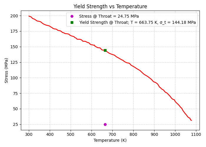
With the temperature-dependent data prepared, we next calculated the total stress ( \sigma_t) at the chamber throat. Initial test calculations showed that thermal stress dominated the total stress budget—often by nearly an order of magnitude compared to mechanical stress. Since RPA identifies the throat as the region experiencing the highest heat flux, this location represents the worst-case thermal loading. The logic follows that if the total stress at the throat remains below the material’s yield strength at that temperature, then the remainder of the chamber—experiencing lower thermal loads—will also remain structurally safe. The figure below shows the web-digitized plot of GRCop-42 yield strength versus temperature, the interpolated yield strength at the throat temperature, and the corresponding total stress we calculated at that temperature.
This calculation resulted in a factor of safety (FOS) of approximately 5, which would only increase during throttled operation. At first glance this seems ideal—however, an FOS this large immediately suggested that something in our assumptions was incorrect. After extensive research and a series of FEA simulations (the latter of which will be discussed in detail in a later section), we discovered the issue: our analytical model treated the cooling channels as an isolated thin ring in vacuum and applied a basic hoop-stress formulation. The figure below illustrates the physical scenario that this simplified equation actually represents:

In reality, several important structural effects were being neglected, the most significant being the presence of the outer wall of the cooling channels, i.e., the cooling jacket. The cooling jacket constrains the thermal expansion of the inner channel walls. As heat flows in from the hot-gas wall, the channels attempt to expand outward, but the jacket restricts this motion. This interaction induces additional thermal and mechanical stresses in the channel walls—far larger than the simple ring stress predicted by the hand calculation.
In conclusion, while these hand calculations are useful for developing intuition about GRCop-42’s material behavior and confirming that basic hoop stresses are small, they are not sufficient to accurately predict the true stress state within the chamber. The only reliable way to evaluate total stress, strain, deformation, and overall survivability is through full FEA analysis using software such as SolidWorks or other high-fidelity structural solvers.
Fuel-boiling Analysis
The temperature of the fuel increases considerably with the inflow of heat in the cooling channels. Excessive increases in temperature could cause the fuel to boiling producing gaseous IPA in the fuel system. The Clausius-Clapeyron equation was used to characterize the boiling point of IPA at the increased temperatures in the cooling channels and at its operating pressure of 500psi. Solving the equation for boiling point, T2, and using enthalpy of vaporization at 20º C provides the following relation:


An improved approximation around the operating parameters was created by using a quadratic regression on experimental values of the enthalpy of vaporization for IPA at high pressures and temperatures. This function can then be used by numerically integrating the Clausius-Clapeyron equation producing the following relation:

Varying the enthalpy of vaporization provides a more accurate characterization of the boiling point over a range of temperatures and pressures based on the values used for the regression. This increased range permits a full characterization of the fuel performance from nominal to the throttled state where its temperature will be elevated.
Material Choice
GrCop-42, a high performing copper alloy with niobium added for elevated performance at high temperautre, was chosen for its superior heat transfer which is especially critical at these engine sizes. Inconel was considered and was verified to be equally functional, in theory.
Fabrication
The chamber was LPBF 3d printed by AME out of GrCop-42 at the end of the 2026 Spring semester. AME handled printing, de-powdering, and heat treating. The part was then handed off to Pro-Cam for 3 post-machining operations: The ORB port and thread for the fuel inlet manifold was added, the injector to chamber face seal was milled to high surface finish (.040" of post-machining was added to allow for post-machining) and the radial O-ring seal between the chamber and injector was milled to a high surface finish (again .040" of post-machining was added to allow for post-machining).