Overview
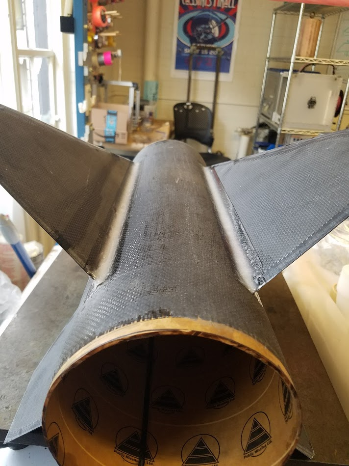
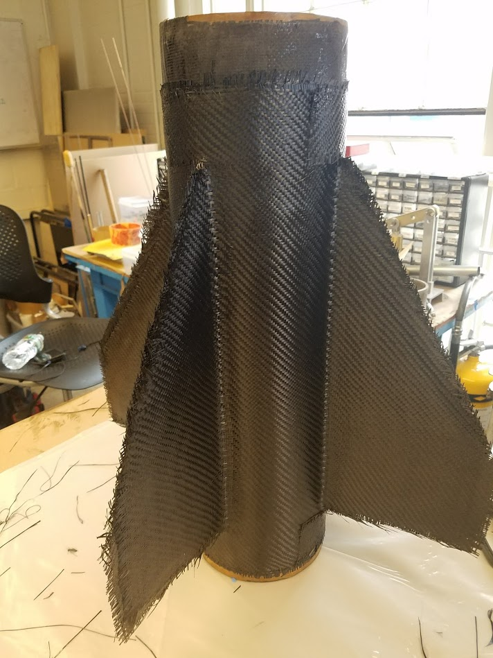
The design for this fin can uses 4 fins, with a phenolic tube overwrapped with carbon fiber as the base and ⅛” G10 fin cores with 12 layers of tip-to-tip carbon fiber on each fin.
The final mass of the fin can was measured to be 5.8 lbs (2.63 kg).
Below are pictures of the Hermes flight fin can.


Manufacturing
Starting with the base, also referred to as the fin collar. We used a 22in long phenolic airframe tube with a 6.007” ID, the next size up is 7”. While both you and me look at this and think, “Oh that will fit over the 6” OD motor case perfectly!”, think again. The motor case was conveniently 6.4ish” OD and while looks were deceiving, it was well out of the sand-to-fit range. So to create a fin collar which fits the motor case the phenolic was cut, slid over the motor case, using it as a mandrel and gluing it back together with 5-minute epoxy. Tips from experience: don’t use slow cure epoxy, don’t tighten the tube around the mandrel too much and use a somewhat stiff release film. At this point you may be asking yourself why we even bothered jumping through all of these hoops some silly phenolic tube. Fear not, I asked myself this same question while spending hours using percussive maintenance to unsuccessfully remove a ratchet-tightened tube from the mandrel. However, since the motor case is structural and the fin can which normally melts at 300F sits directly on the aft end of that case, we need some thermal protection and so we used phenolic, an excellent thermal insulator. So once we had the phenolic tube at the appropriate size, it was ready for overwrap, which was far less dramatic as most overwrap issues were related to the phenolic cutting and re-gluing nonsense. Three wraps of 2x2 5.7oz twill weave carbon fiber was used (plain weave works just as well). A fair amount of extra carbon was used for this because an extra inch or two in the front of the 16” long fins is needed as well as extra length to make clean cuts on the front and back of the fin can, ie. if the CF fabric ends at the edge of the fin can, you will have a messy edge. We heat shrinked this part when we let it cure because being smooth was the priority, wrinkles would be sad. Also peel ply is one of your best friends for all the layups in this fin can.
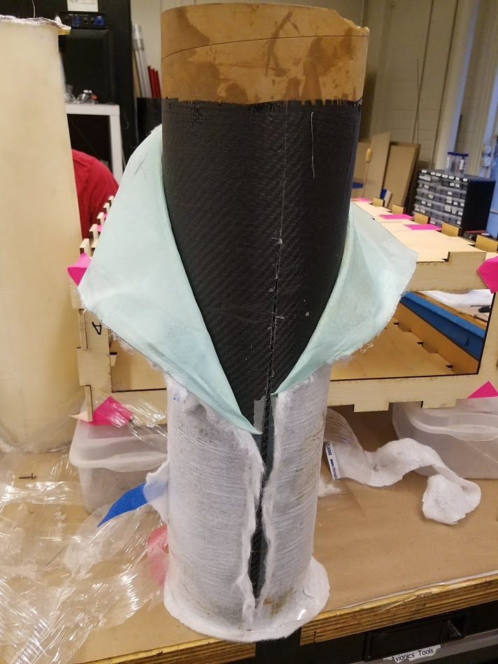

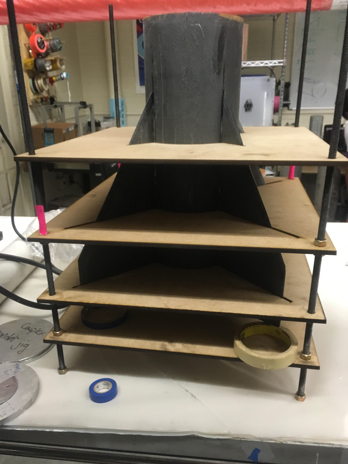
Now it’s time for the fin jig, we used a newer fin jig for this fin can which uses 4 sheets of plywood with laser cut patterns for the tube and fins to keep the fins aligned at the same height with no cant or unintended angle of attack. The fin jig panels were aligned with 4 threaded rods and held up by nuts at specific positions along each of the rods to keep the panels flat. If this description makes no sense to you like it wouldn’t to me hopefully the pictures help. The “fins” that were attached at this step were really just the waterjet G10 fin cores, also called fin preforms (I don’t make these names I just roll with them). These were water jet to shape and had bevels sanded around the edges, then were epoxied to the fin collar using the fin jig leaving tube in front and behind the fins. Once the fins were tacked on to the collar, fillets, which hold a large portion of the strength keeping the fins on the rocket, were added. We used 24-hour epoxy with filler to make .5in radius fillets, although a less stiff adhesive is ideal. Protip: use masking/painters tape to mark the radius of the fillet then make the fillet (we used a 3D printed tool) and remember to peel off the tape while the epoxy is still wet. Clean up those fillets with some sand paper and loud music and you my friend are ready for a fun 8 hour tip-to-tip layup.
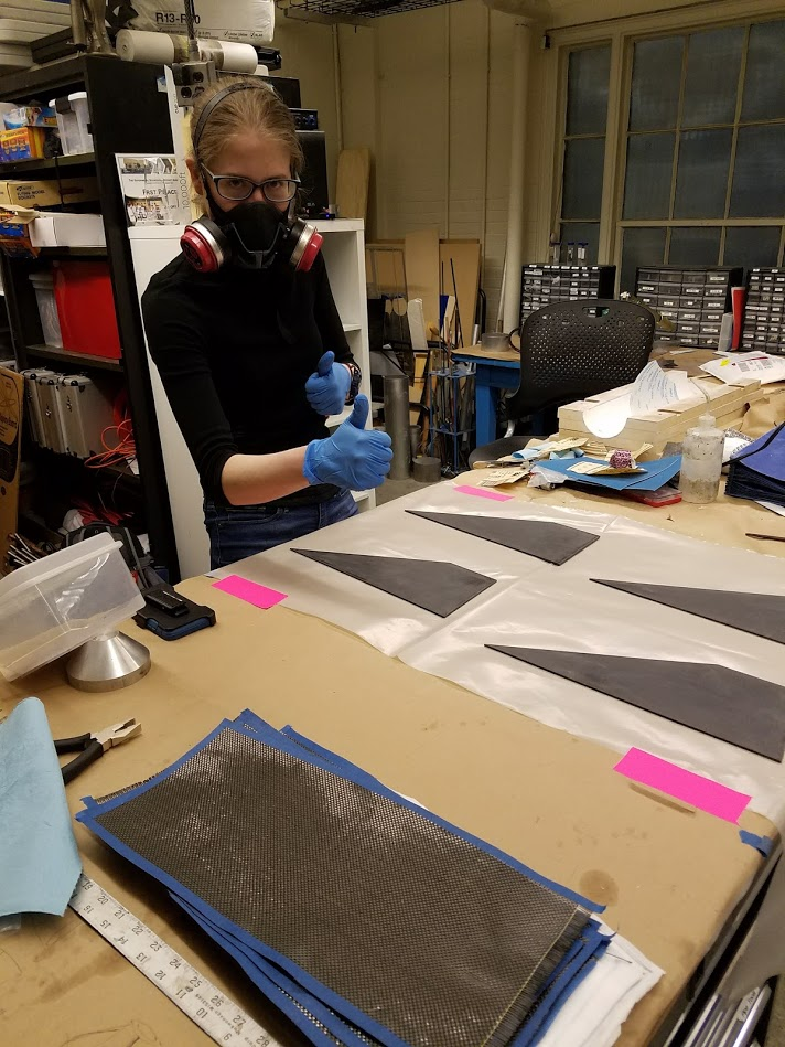
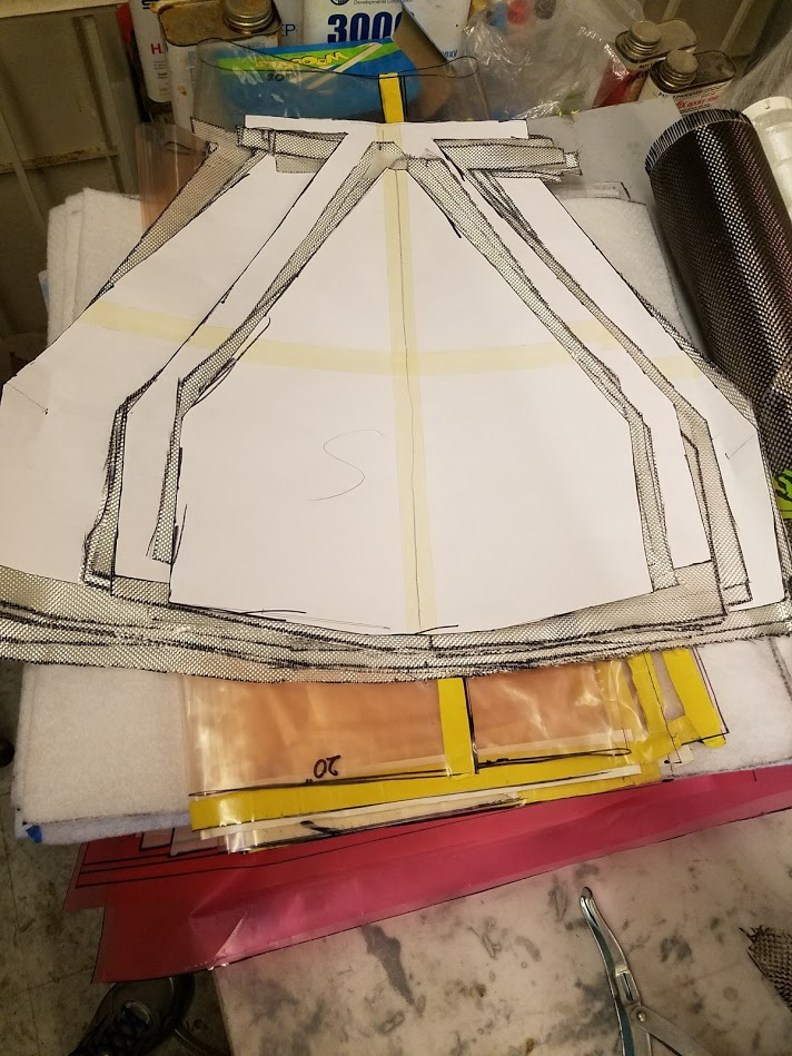
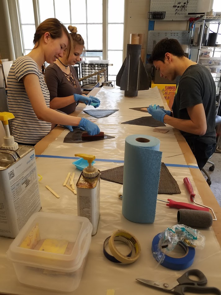
Back to the rather large pile of carbon that still needs to go into this fin can. This fin can uses six layers of tip-to-tip 5.7oz carbon fiber 2x2 twill weave fabric, the twill helps a little in this case with conforming to the shape of the fins and fillets. Since there are six tip-to-tip layers, that means that there are six layers of carbon fabric that stretch from one fin around the tube and up to the next fin (from the tip of one fin to the tip of the next right). But don’t jump any guns, this means that each fin has not six but 12 layers of carbon, six on each side. We chose to have 2 layers that don’t reach all of the way to the tips of the fins, 2 more layers that were larger but didn’t quite reach the tips and only 2 layers that were truly tip-to-tip. This small, medium, large carbon layer configuration with offsets from the tip of 2”,1”, 0 respectively were chosen because this gives the fins a smoother contour for better aerodynamics and a smoother layup at the cost of some strength. If you are trying to model the strength of the tip-to-tip...good luck, it’s pretty challenging since no fin modelling programs I know take tip-to-tip as an input, and I’m not about to do all of those tensor matrices myself, maybe some FEA wizard can do it. But I’m no wizard, I’m just a boy. A little trick I straight up stole from DBF, thanks guys, is that when cutting shapes in dry fabric it usually helps to spray glue them to a sheet of wax paper. Make it pretty light, like stickiness of a fruit sticker. This is really useful when you have to store them because it keeps them from warping. For this fin can to be extra fancy, we cut the desired shapes for all of the layers with a laser cutter. This is super useful because the layers will be cut faster and more accurately. Also don’t listen to the skeptical MechEs who have a monopoly on the laser cutters, most laser cutters can cut CF no problem, use high power low speed, but it MUST be dry, you cannot laser cut any composites with epoxy cured or uncured. If you notice there are flappy little tabs on the top and bottom of the tip-to-tip sheets and that’s to ensure a smoother transition and a little extra strength. If you really want your fin can to be smooth then you should dremel/sand out the regions where the flaps overlap before the layup. Before we slapping epoxy around remember to mark a centerline halfway between each fin and on at least the first round of tip-to-tip sheets. You know I said a while ago we were ready for the layup, this is where you actually do that part. Squeegees and rollers are your friends. We laminated the sheets on a table to control the epoxy better. Be really careful taking the fabric off of the wax paper so you don’t warp it and in general because warped fabric is sad and will make you sad also. Also I wasn’t kidding with the time frame on this layup, having a team of at least 3 or 4 with people who are practiced with this kind of layup will help a lot. Vacuuming this bad boy can be a struggle, we bagged from the inside and outside using a vacc bag cylinder in the middle and a kind of cross-shaped assembly of bag for the outside. Protip: always leave plenty of extra margin on the vacc bag sizing. Gave it some good suction, threw it in an oven, and out popped our neato fin can. Time to find yourself some good sandpaper and good music...a lot of good music. Since our fin can is expected to go kinda fast, we will get some heating especially around the edges. We lined the edges with hi-temp epoxy to help mitigate that, yes it’s not the ideal TPS but I can only do so much. A little more sandpaper, maybe a nice paint job, and look at that a nifty fin can ready for some rootin tootin rocket shootin. Shoutout to the VP for the crazy amount of sanding at the end which I did absolutely none of since I fled the country when we got to the sanding stage of the year.
Older fin can bc i dont have pic of new stencils

Below is the layup schedule.
| Date | Result |
|---|---|
| November 13, 2017 | Subscale e-glass layup. Many lessons learned |
| December 9, 2017 | Subscale e-glass layup. More Lessons learned |
| January 20, 2018 | Fullscale e-glass layup. Small defects |
| February 25, 2018 | |
| April 29, 2018 | Flight Fin Can Layup. Carbon and G10 |