Sub-assemblies
Motor
5/16", 1/4" hex key
- Epoxy
- High temperature grease
- Gorilla glue/polyurethane (PU) glue
- Room temperature vulcanizer (RTV)
- Adjustable spanner
- Rubber Mallet
- Boattail Allen Key**
...
NOTE: This page will likely be later updated so that each major sub- assembly is a separate page
Sub-assemblies
...
- Assemble the nozzle. Add o-rings and lubricate well.
- Follow the 'MIT Rocket Team Grain Cutting and Bonding Procedure' to bond the grains to the liner, using the nozzle assembly as a placement guide. Apply aeropoxy to the splice, if any.
- Bolt the nozzle assembly to the case, taking account of directionality.
- Slide the motor load into the case.
- Use RTV to attach the insulation disk to the forward closure.
- Attach the pressure transducer to the forward closure.
- Add o-rings to the forward closure and lubricate generously. Slide the closure into the open end of the case.
- Bolt the forward retention ring to the case.
Piston
MaterialsPIston
1/4 in torque wrench
- Integrated
...
- Firebolts
- Multimeter
- Teflon tape
- 2 1/4 NPT
...
- plugs
- Safety goggles
- Gloves
...
- Weigh boats
- Popsicle sticks
- Elbow joint
- Tee fitting
- Adjustable wrench
- Vice grip/pliers
...
- Small scale
Procedures
Using a 1/4 inch torque wrench, ensure that the bolts holding the piston together are very very tight. If the bolts are loose, the piston will lose pressure as it extends. (torque wrench adapter in piston box)
Use multimeter to check continuity of Firebolt (should be about 1.0-1.4 ohms) and twist the wires to short it. Two people should visually confirm that it is shorted. Wrap the Firebolt with five wraps of Teflon tape. Use pliers to screw firebolt into the NPT plug.
Everyone put on safety glasses. From now on, everyone within the vicinity of the pyrotechnics must wear safety glasses.
Measure
- Small scale
...
and pour 0.2 g of black powder into
...
the other side of the
...
plug, holding over a weigh boat to catch any fallout. Seal the opening by wrapping over the head and opening three times with Teflon tape. Make sure Teflon tape is flush on the inside.
Repeat steps b-d
Compress the piston completely!
Screw an elbow joint into a side female end of the tee after adding Teflon tape.
Wrench the elbow and tee assembly into the inlet hole of the piston with 5 wraps of Teflon tape until extremely tight and turned upright.
...
Screw a 1/4 NPT plug into a female end of a 1/4 NPT tee adapter.
...
Seal the open female end of the tee fitting with another plug (filled with appropriate black powder).
Payload - NC
...
AV Tower
Soft Goods
...
Materials
...
Parachute Packing Box (shot bag, line holder, extra lines)
- Sandbags
- Rubber bands
- Soft goods
- Swivels box
- Flathead screwdriver
...
Procedures
...
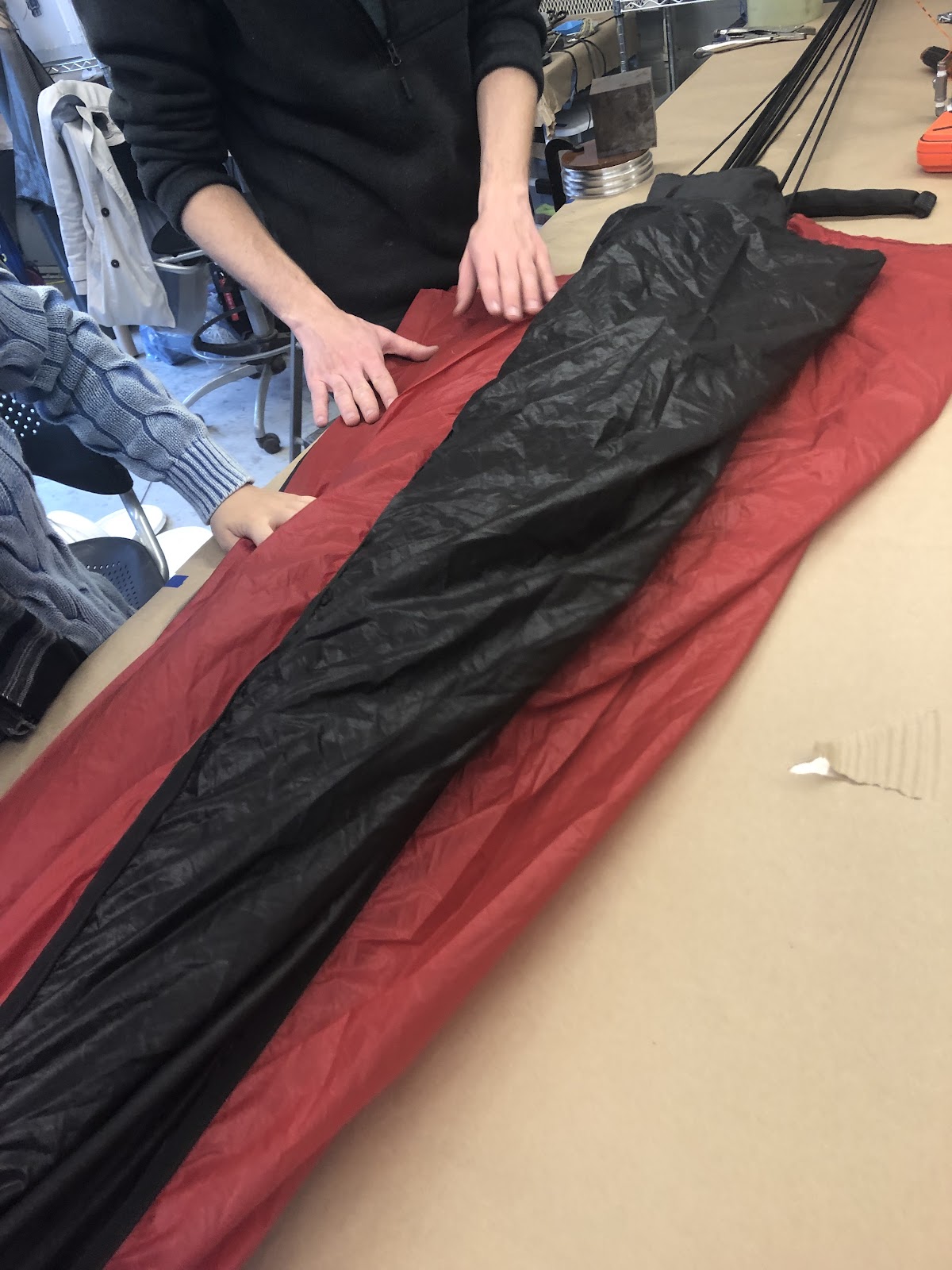
Fold Main (also may refer to Hermes Parachute Packing Procedures)
...
Tie main parachute down, at the vent and at the end of lines, applying moderate tension.
...
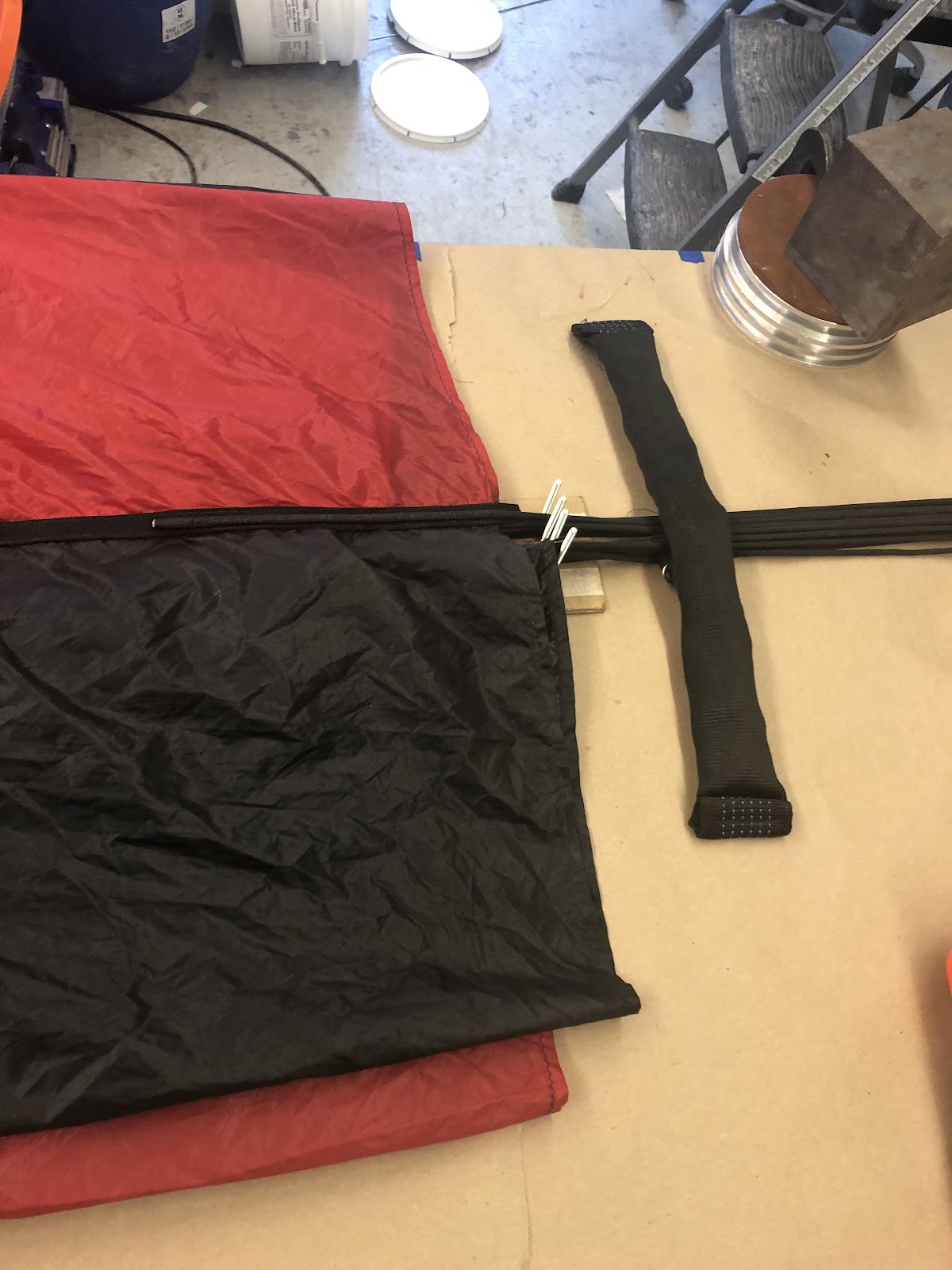
Gather 8 lines and put them into the lines holder with weights, so you can focus on the other 8 lines.
...
Go through each line and gore, inspecting gores for tears
...
Pleat gores so middles are together and put the lines in the holder as you go.
...
Once you've nicely folded one side (8 lines and gores), weigh down with sandbag and fold over other side to repeat
...
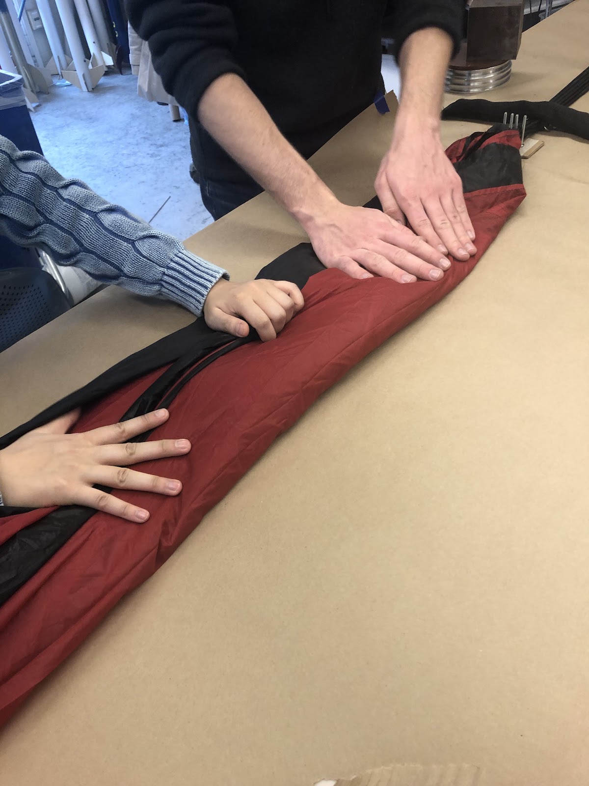
Fold up base of parachute towards middle in a triangle pattern
Put the 2 assembled plugs into two remained female ends of tee fitting
Clock the tee fitting close to the body of the piston so the piston fits better into AV bay
- Test the piston by pulling up rod for 5 secs and seeing it it is sealed
- Log Firebolts
Nosecone Tip Procedure
Procedures
- put bolt through washers
- put thermocouples through washers
- twist both sides of wires (wrap around bolts and thermocouples around themselves
- stick into NC to the end, pull themocouples through small end. Shift around to place washers flat inside
- put nosecone tip in
- stick a long arm in and twist the bolt into hole
Payload - NC
AV Tower
Soft Goods
Lower Electronics
https://docs.google.com/document/d/1iBwlQAUkS_-ASFAVhsMO-ndsaEsJqW-zG7LUMhQ1ETo/edit?usp=sharing - full integration guidelinesMP Assembly
Hermes II Mission Package Assembly Procedures
Fold the wider sides of the parachute in towards the center line, using sandbags for assistance
...
Untie top of parachute from tension
...
Pull vent to bag bridle through the inside of the bag and the hole at the end. Secure bag handles and vent to bag bridle with a quick link.
...
Pull the inner layer of flaps forward so the bag is partially inside out
...
Z fold the parachute and pack it into the bag.
...
Once the entire parachute is in the lower portion of the bag, securing flaps using the locking loop and locking pin.
...
Fold lines into bites, secure two bites with rubber bands on both ends. Secure spectra in z fold with 2 rubber bands.
...
Pack Drogue
Similar to main
Secure flaps with banding system (TBD)
Figure 8 lines, pack lines into side pocket.
...
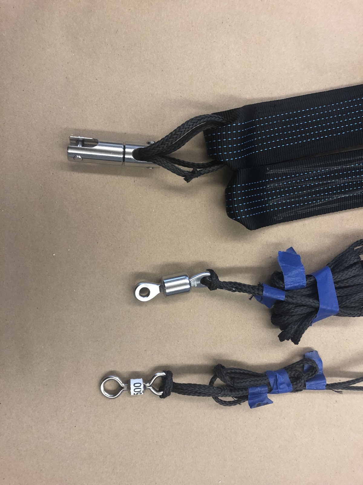
Coil lines
Get green swivels/hardware box and lines and risers
Drogue riser (infinity loops)
Attach eye to eye swivel
Motor section riser (2 coils, (infinity loops)
Attach fork to fork swivel using motor riser loop
Tighten forks hard!
Mission package riser ((infinity loops)
Attach smallest swivel
Mystery Box
MP Assembly
Materials
- Hard goods box (6-32 bolts, 4 1/4-28 bolts, 4 1/4-28 bolts with washers, 3 chamfered 6-32 bolts, eyenut, cotter pin, 10-32 nuts, quicklinks)
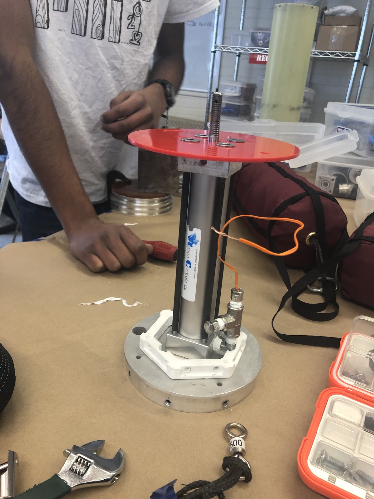
- Integrated piston
- AV tower
- Recovery guard
- Payload stack
- Payload bulkhead
- NC coupler
- Antirotation rod
- Skinny god nut
- Integration stands
- Tender descenders and loops
- Black Powder
- Gloves
- Goggles
- Paper funnel
- Scale
- Hex key set
- Needle nose pliers
- Adjustable wrench
- Clocking tool
...
Procedures
...
Attach AV tower to payload bulkhead with 6-32 bolts
Attach integrated piston to payload bulkhead with ¼ 28 bolts
Wire piston to AV tower
Attach recovery guard to piston using ¼ 28 bolts and washers
Attach payload stack to payload bulkhead
Attach nosecone coupler using 3 chamfered 6-32 bolts, attach nosecone
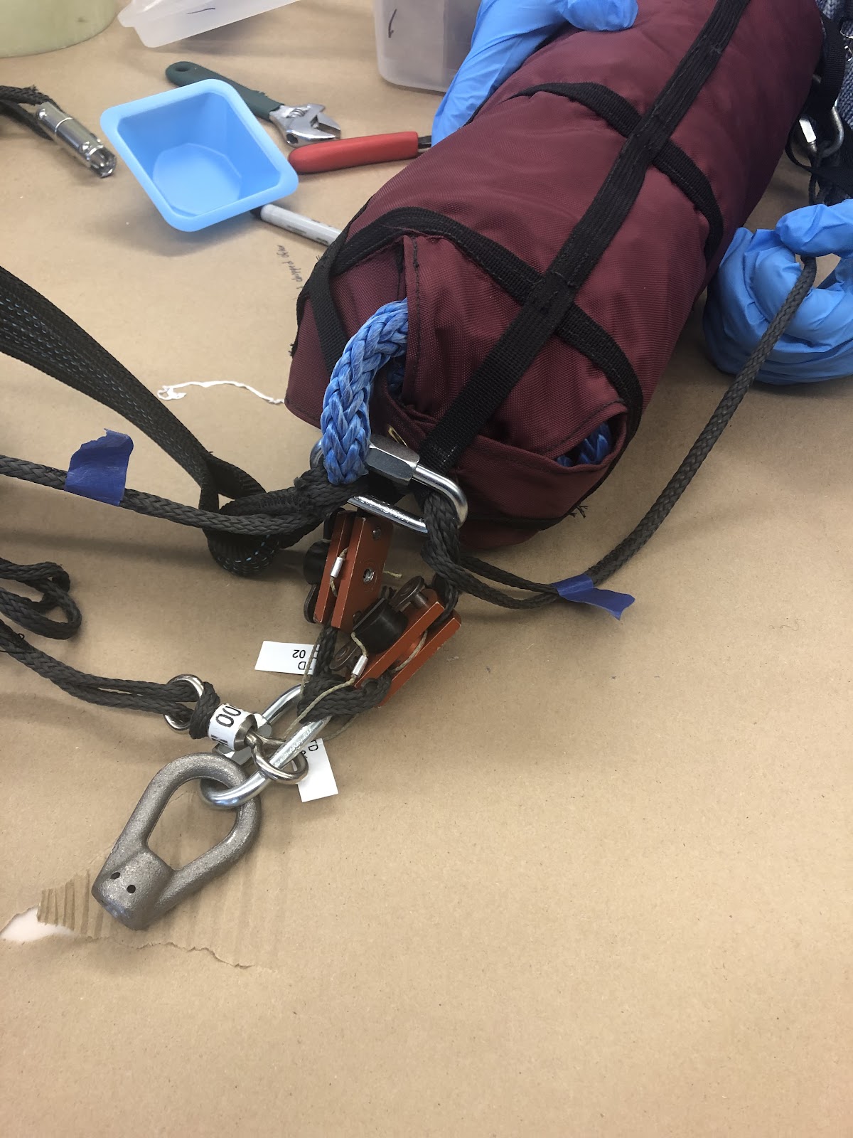
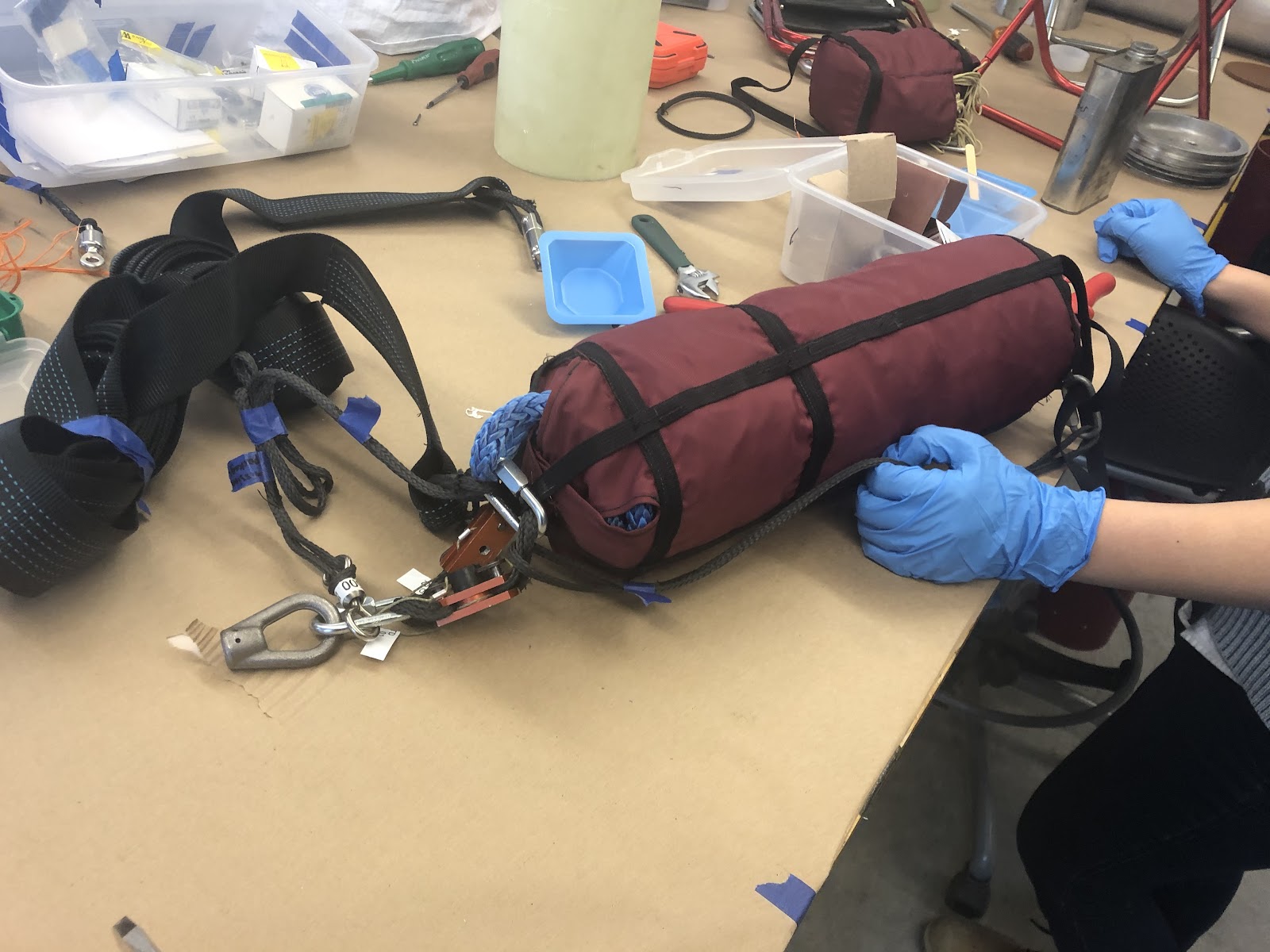
Integrate soft goods with Tender descender: Just follow the picture it’s super complicated. Tighten all quick links with a wrench
Screw antirotation rod into diaphragm with locknut
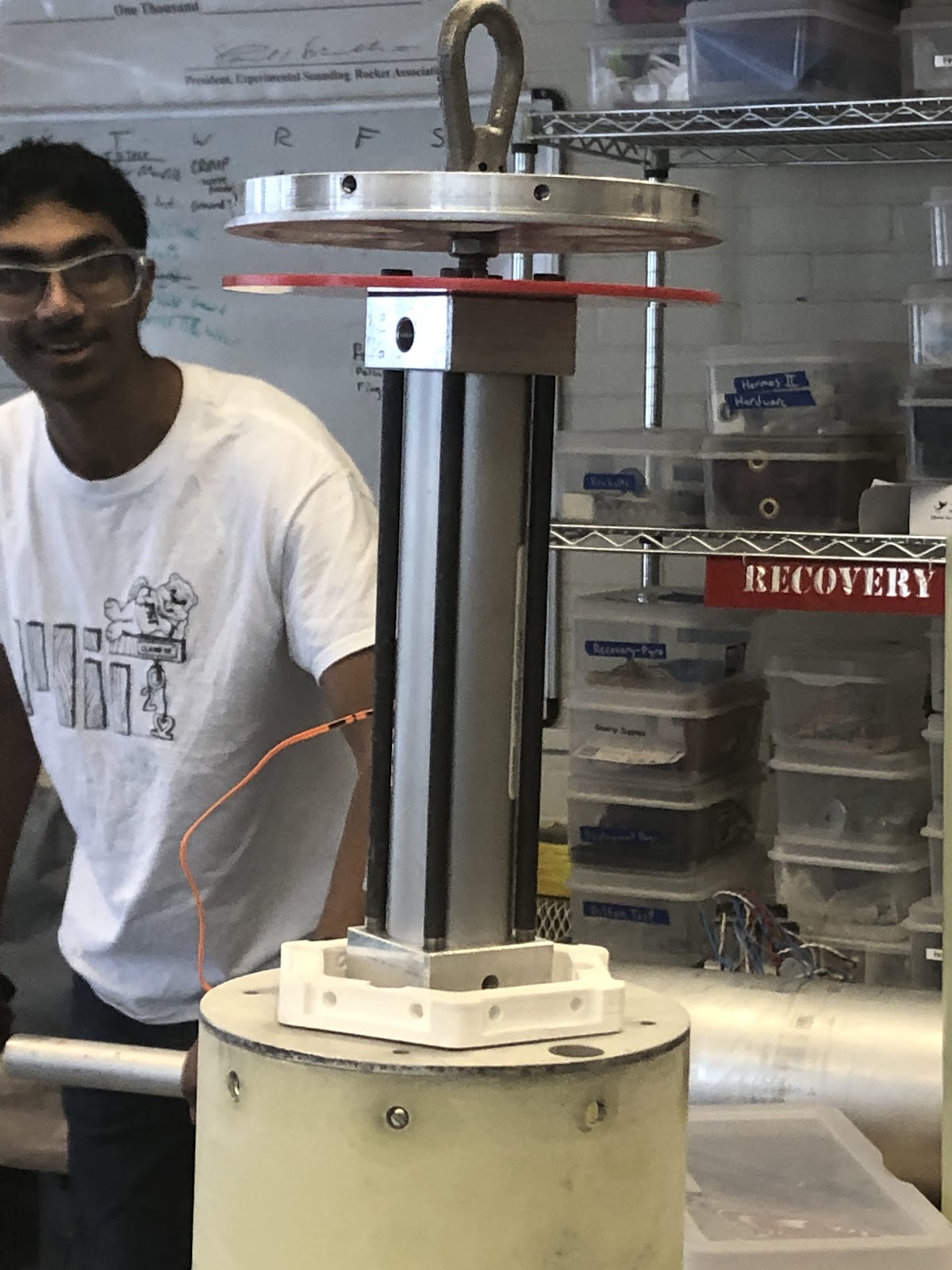
Attach diaphragm. Screw on skinny god nut and place diaphragm on. Next screw the eye nut on and insert cotterpin.. Finally, hold the skinny god nut with small pliers and screw the eye nut tight. Fold down and gaff tape over the spikey bits of the cotterpin!
Set up integration stands. Stand piston-diaphragm assembly and cup close to each other.Thread main bag with lines and tender descenders through cup, so tender descenders are close to the diaphragm. Pull tender descender wires through half-moon shaped hole and attach tender descenders to eye nut.
Push cup (with main bag, TDs and lines) onto diaphragm and secure with 10-32 nuts
Attach swivel (on motor riser) to quick link on top of main bag
Quick link drogue to drogue riser
Integration Order
Ideally, the piston, AV tower, and payload stack can be
...
assembled in parallel and then each attached to the payload bulkhead. In parallel to this assemblage, the nosecone and mystery box can be integrated. Then the two groups would be integrated together with the soft goods and the fin can.
...
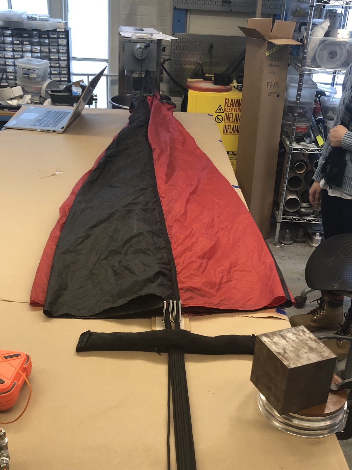
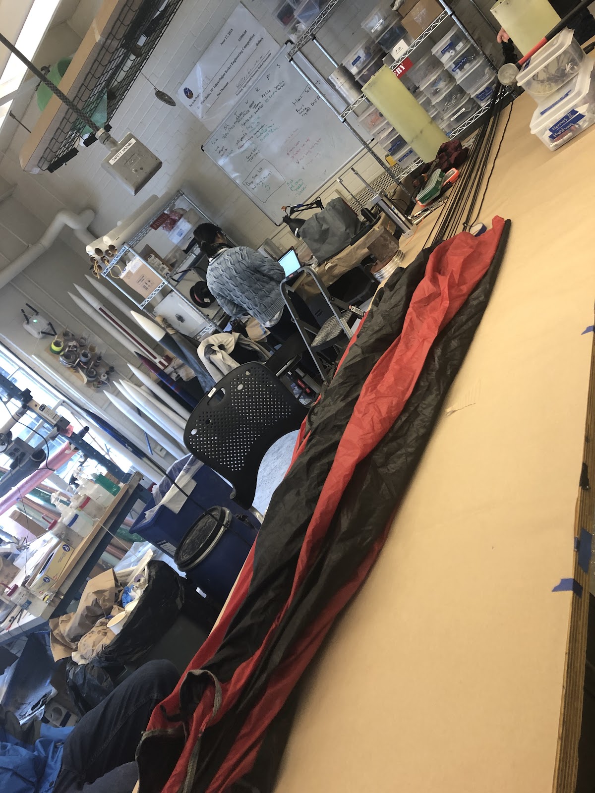
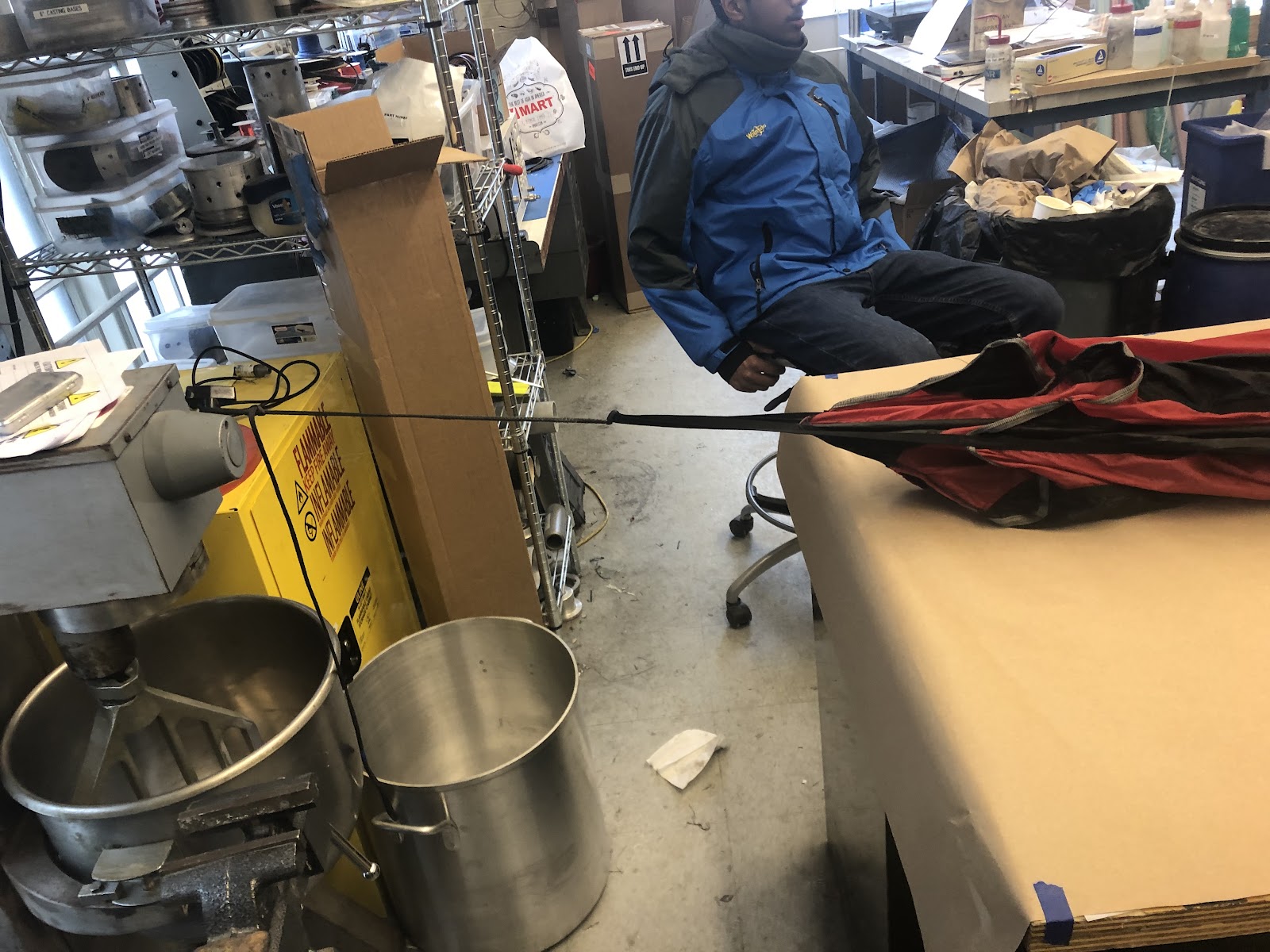
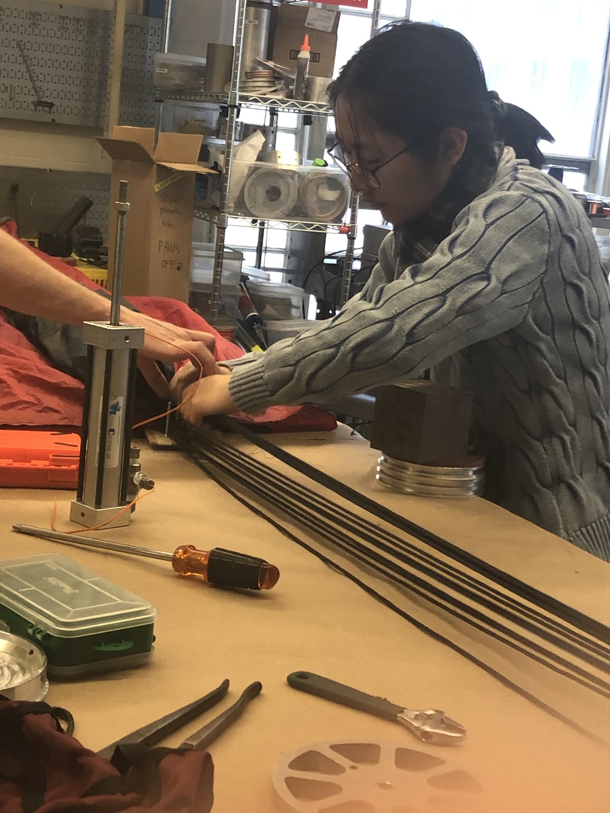
Soft Goods Assembly Pictures

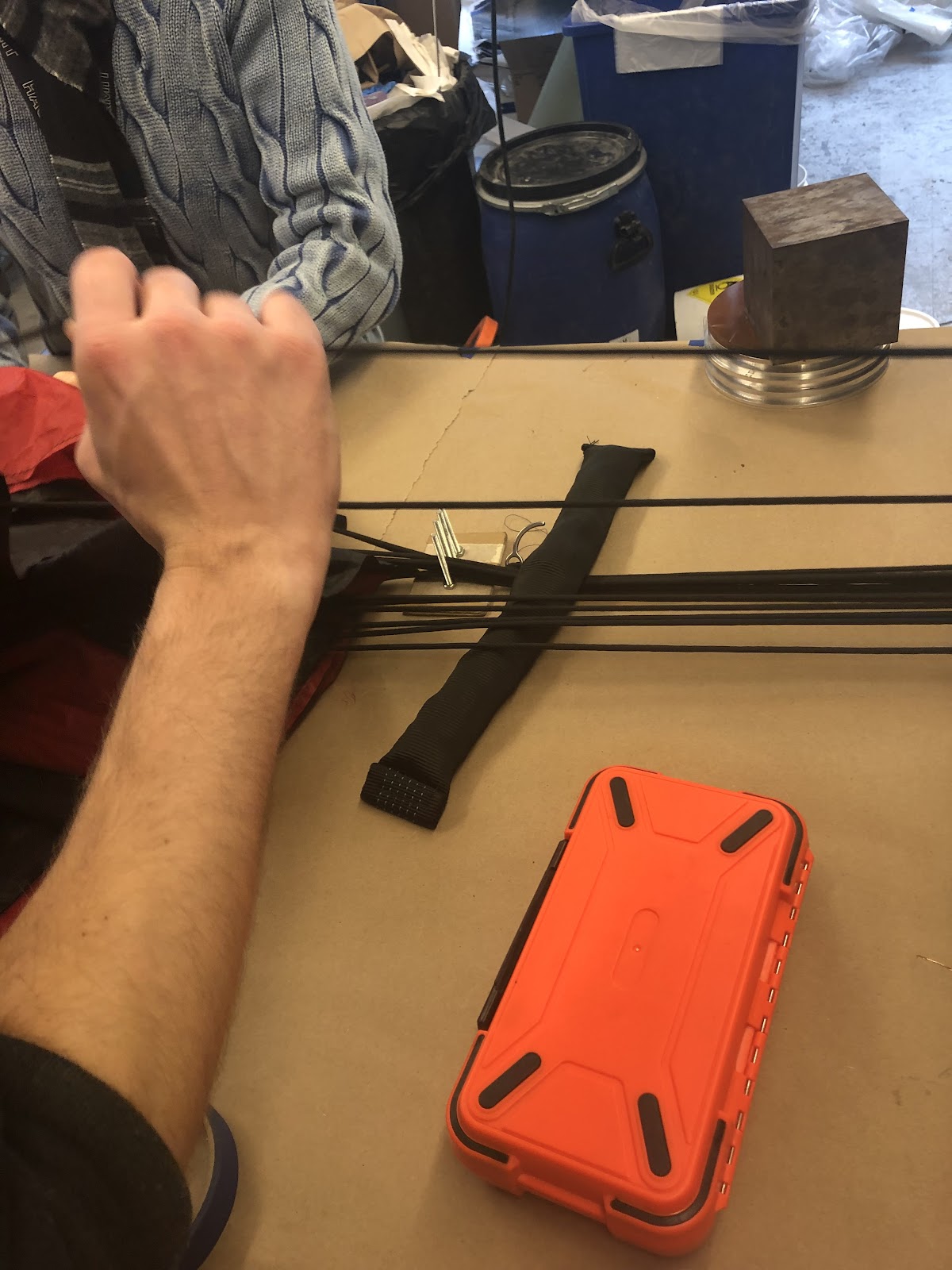


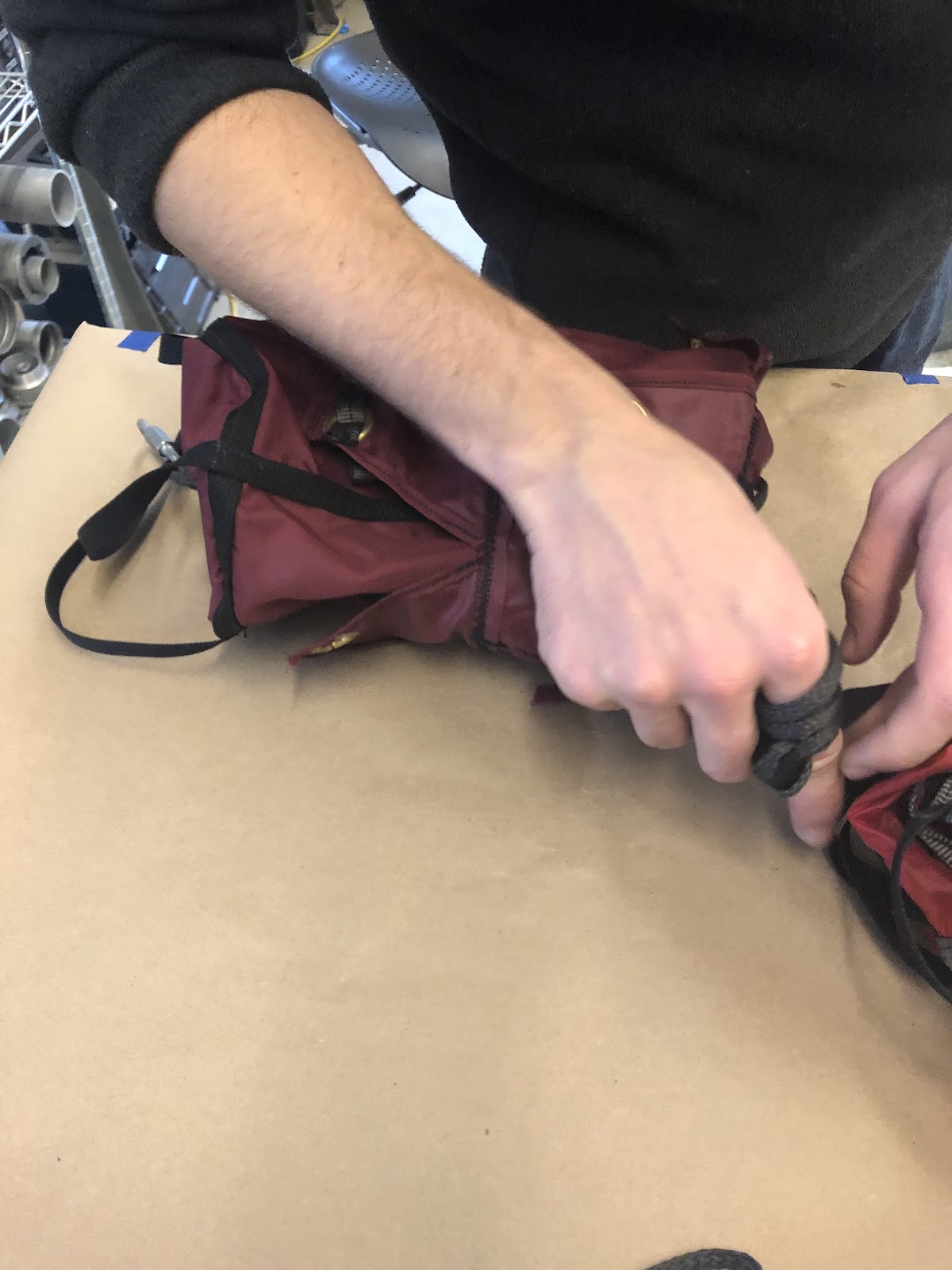

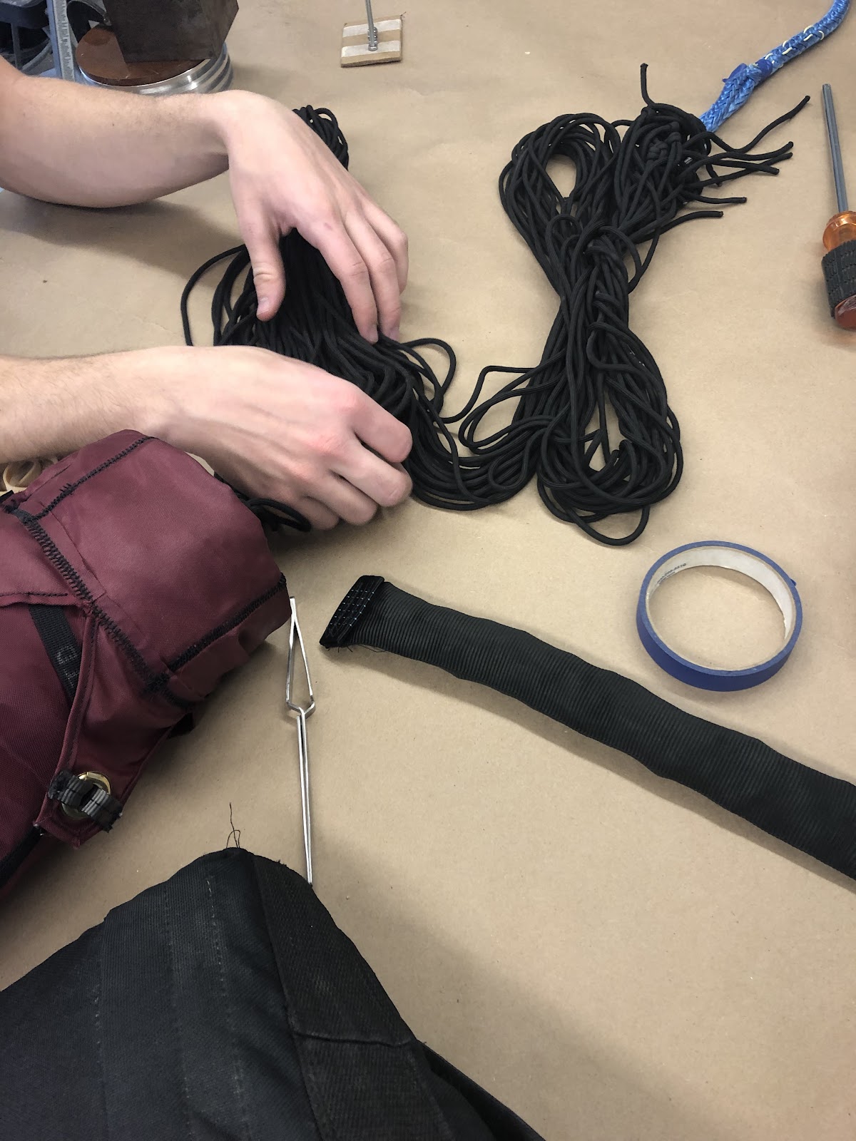
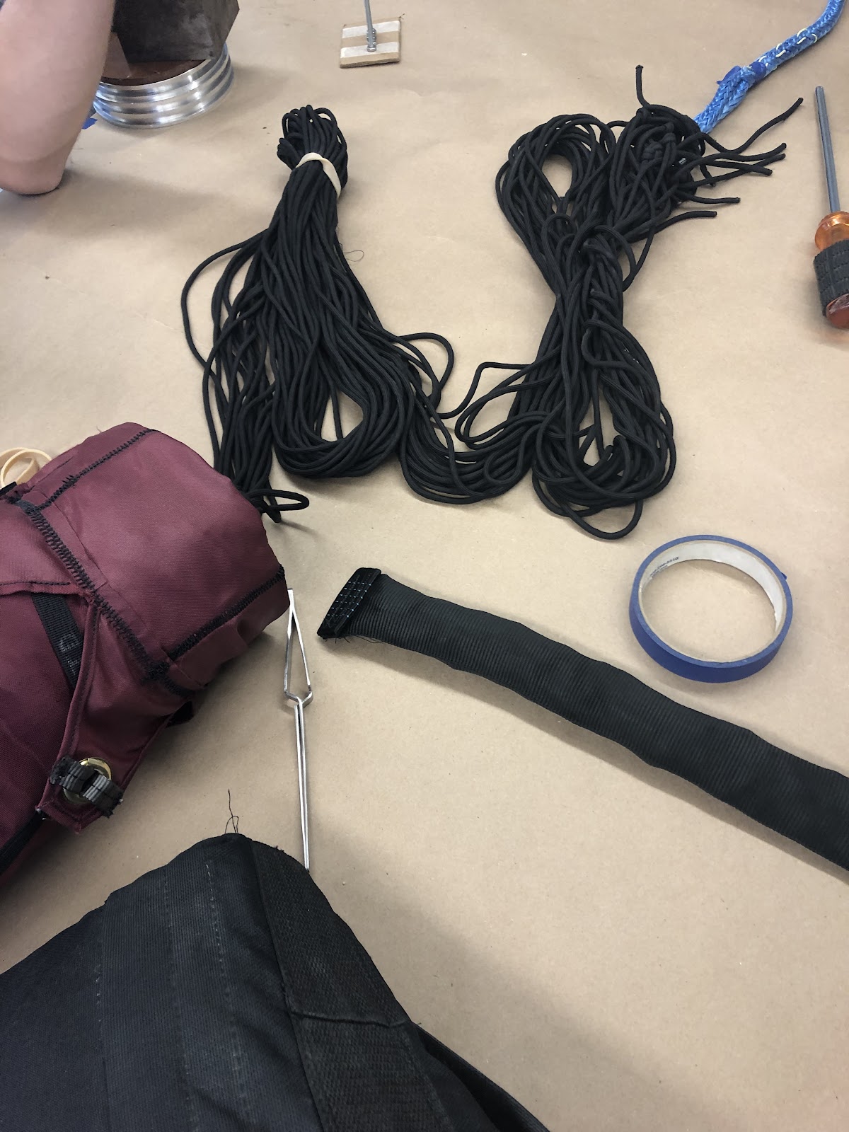
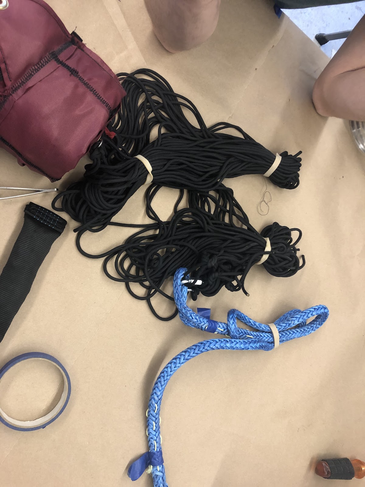

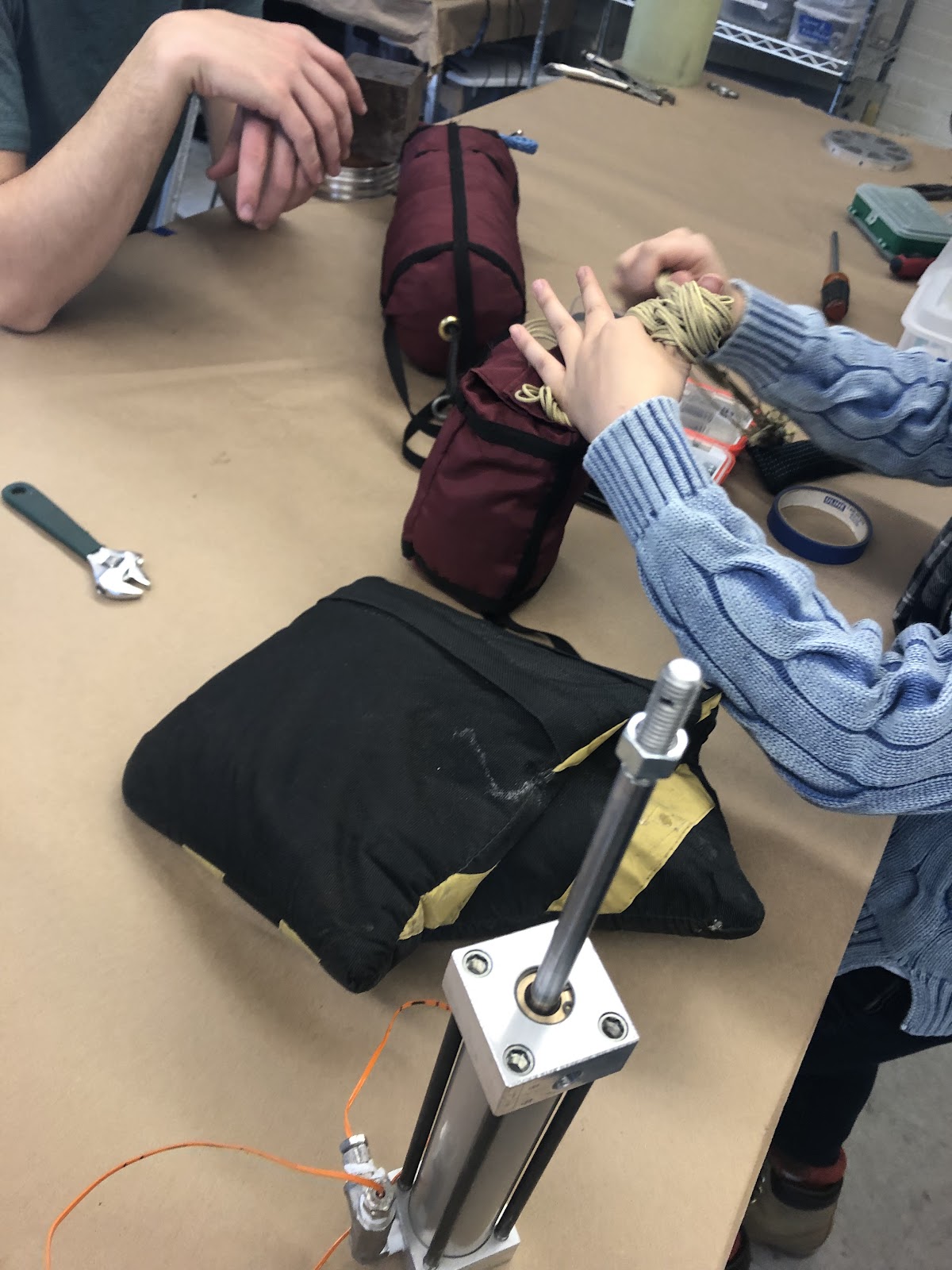

MP Assembly Pictures
...